


MDS-E/EH Series Instruction Manual
4 Setup
217
IB-1501229-F
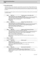
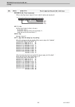
[For semi-closed loop]
Set the same value as SP020 (RNG2). (Refer to the explanation of SP020.)
[For full-closed loop]
Set the number of pulses per revolution of the machine side encoder.
When using the encoder interface unit MDS-EX-HR, use this with SP097(RNG1ex).
Encoder
OSE-1024 (ABZ pulse): SP019=4096, SP097=-1
TS5690( 64 teeth): SP019 = 2000, SP097=0
TS5690( 90 teeth): SP019 = 2880, SP097=0
TS5690(128 teeth): SP019 = 4000, SP097=0
TS5690(192 teeth): SP019 = 6000, SP097=0
TS5690(256 teeth): SP019 = 8000, SP097=0
TS5690(384 teeth): SP019 =12000, SP097=0
ERM280(1200 teeth): SP019 = 4800, SP097=0
ERM280(2048 teeth): SP019 = 8000, SP097=0
MPCI : SP019 = 7200, SP097=0
MBE205: SP019 = 2000, SP097=0
GEL2449M(524,288(p/rev)): SP019=0, SP097=8
---Setting range---
When SP097=0, the setting range is from 0 to 32767 (kp)
When SP097
≠
0, the setting range is from 0 to 65535 (p)
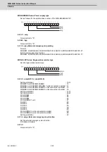
Set the number of pulses per revolution of the motor side encoder. Set the standard parameters for the motor
with frame.
---Setting range---
When SP098=0, the setting range is from 0 to 32767 (kp)
When SP098
≠
0, the setting range is from 0 to 65535 (p)
Set the detection time constant of Overload 1 (Alarm 50). (For Mitsubishi adjustment)
Normally, set to "60".
Set to "300" when using an IPM spindle motor.
---Setting range---
1 to 15300 (s)
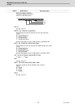
Set the current detection level of "Overload 1" (Alarm 50) as a percentage against the motor short-time rated
output current. (For Mitsubishi adjustment)
Normally, set to "120".
Set to "100" when using an IPM spindle motor.
---Setting range---
1 to 200 (Short-time rated %)
Set the excessive error detection width for the interpolation mode and spindle synchronization.
The standard setting is "120".
When set to "0", the excessive error detection will be ignored, so do not set to "0".
---Setting range---
1 to 32767 (°)
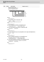
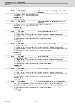
(PR)
#13019
SP019 RNG1
Sub side encoder resolution
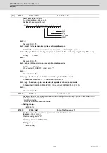
(PR)
#13020
SP020 RNG2
Main side encoder resolution
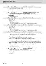
(PR)
#13021
SP021 OLT
Overload detection time constant
#13022
SP022 OLL
Overload detection level
#13023
SP023 OD1
Excessive error detection width (interpolation mode -
spindle synchronization)
Summary of Contents for MDS-E
Page 1: ......
Page 3: ......
Page 15: ......
Page 17: ......
Page 19: ......
Page 21: ......
Page 31: ......
Page 32: ...1 IB 1501229 F 1 Installation ...
Page 76: ...45 IB 1501229 F 2 Wiring and Connection ...
Page 132: ...101 IB 1501229 F 3 Safety Function ...
Page 142: ...111 IB 1501229 F 4 Setup ...
Page 277: ...MDS E EH Series Instruction Manual 4 Setup 246 IB 1501229 F ...
Page 278: ...247 IB 1501229 F 5 Servo Adjustment ...
Page 351: ...MDS E EH Series Instruction Manual 5 Servo Adjustment 320 IB 1501229 F ...
Page 352: ...321 IB 1501229 F 6 Spindle Adjustment ...
Page 404: ...373 IB 1501229 F 7 Troubleshooting ...
Page 455: ...MDS E EH Series Instruction Manual 7 Troubleshooting 424 IB 1501229 F ...
Page 456: ...425 IB 1501229 F 8 Maintenance ...
Page 475: ...MDS E EH Series Instruction Manual 8 Maintenance 444 IB 1501229 F ...
Page 476: ...445 IB 1501229 F 9 Power Backup System ...
Page 494: ...463 IB 1501229 F 10 Appx 1 Cable and Connector Assembly ...
Page 504: ...473 IB 1501229 F 11 Appx 2 D A Output Specifications for Drive Unit ...
Page 514: ...483 IB 1501229 F 12 Appx 3 Protection Function ...
Page 523: ...MDS E EH Series Instruction Manual 12 Appx 3 Protection Function 492 IB 1501229 F ...
Page 524: ...493 IB 1501229 F 13 Appx 4 Compliance to EC Directives ...
Page 528: ...497 IB 1501229 F 14 Appx 5 EMC Installation Guidelines ...
Page 540: ...509 IB 1501229 F 15 Appx 6 Higher Harmonic Suppression Measure Guidelines ...
Page 550: ......
Page 554: ......


