MDS-E/EH Series Instruction Manual
4 Setup
116
IB-1501229-F
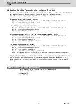
4.2.1 Setting of Servo Specification Parameters
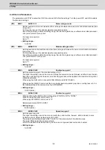
(1) Basic specification parameters
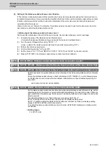
When performing absolute position control, set the axis specification parameter #2049. When the setting value of
#2049 is "1 to 4", "SV017/bit7" is automatically set to the absolute position control.
It is not possible to set SV017/bit7 directly.
【
#2049(PR)
】
type Absolute position detection method
Select the absolute position zero point alignment method.
0: Not absolute position detection (Incremental control)
1: Stopper method (push against mechanical stopper)
2: Marked point alignment method I (The grid point is the reference position.)
3: Dog-type (align with dog and near point detection switch)
4: Marked point alignment method II
(The position with which the mark was aligned is the reference position.)
9: Simple absolute position (Not absolute position detection, but the position when the power is
turned off is registered.)
【
#2217(PR)
】
SV017 SPEC1 Servo specification 1
bit 7 : abs Position control
These parameters are set automatically by the NC system.
0: Incremental 1: Absolute position control
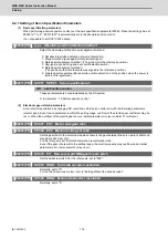
(2) Electronic gear related parameters
Servo control is performed by changing NC command unit to servo control unit with the following parameters
(electric gear). Even if each parameter is within the setting range, overflow of the electric gear coefficient may be
occur. When the overflow of the electric gear occurs, initial parameter error (servo alarm 37) will occur.
【
#2201(PR)
】
SV001 PC1 Motor side gear ratio
【
#2202(PR)
】
SV002 PC2 Machine side gear ratio
Set the gear ratio in the machine side when there is the gear between the servo motor's shaft and
machine (ball screw, etc.).
For the rotary axis, set the total deceleration (acceleration) ratio.
Even if the gear ratio is within the setting range, the electronic gears may overflow and an initial
parameter error (servo alarm 37) may occur.
【
#2218(PR)
】
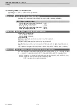
SV018 PIT Ball screw pitch/Magnetic pole pitch
Set the ball screw pitch. For the rotary axis, set to "360".
【
#2219(PR)
】
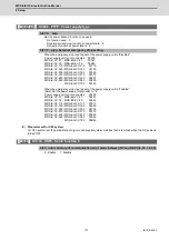
SV019 RNG1 Sub side encoder resolution
Normally, set to "0".
For the full-closed loop control, refer to "Setting of Machine Side Encoder".
【
#2220(PR)
】
SV020 RNG2 Main side encoder resolution
Normally, set to "0".
Summary of Contents for MDS-E
Page 1: ......
Page 3: ......
Page 15: ......
Page 17: ......
Page 19: ......
Page 21: ......
Page 31: ......
Page 32: ...1 IB 1501229 F 1 Installation ...
Page 76: ...45 IB 1501229 F 2 Wiring and Connection ...
Page 132: ...101 IB 1501229 F 3 Safety Function ...
Page 142: ...111 IB 1501229 F 4 Setup ...
Page 277: ...MDS E EH Series Instruction Manual 4 Setup 246 IB 1501229 F ...
Page 278: ...247 IB 1501229 F 5 Servo Adjustment ...
Page 351: ...MDS E EH Series Instruction Manual 5 Servo Adjustment 320 IB 1501229 F ...
Page 352: ...321 IB 1501229 F 6 Spindle Adjustment ...
Page 404: ...373 IB 1501229 F 7 Troubleshooting ...
Page 455: ...MDS E EH Series Instruction Manual 7 Troubleshooting 424 IB 1501229 F ...
Page 456: ...425 IB 1501229 F 8 Maintenance ...
Page 475: ...MDS E EH Series Instruction Manual 8 Maintenance 444 IB 1501229 F ...
Page 476: ...445 IB 1501229 F 9 Power Backup System ...
Page 494: ...463 IB 1501229 F 10 Appx 1 Cable and Connector Assembly ...
Page 504: ...473 IB 1501229 F 11 Appx 2 D A Output Specifications for Drive Unit ...
Page 514: ...483 IB 1501229 F 12 Appx 3 Protection Function ...
Page 523: ...MDS E EH Series Instruction Manual 12 Appx 3 Protection Function 492 IB 1501229 F ...
Page 524: ...493 IB 1501229 F 13 Appx 4 Compliance to EC Directives ...
Page 528: ...497 IB 1501229 F 14 Appx 5 EMC Installation Guidelines ...
Page 540: ...509 IB 1501229 F 15 Appx 6 Higher Harmonic Suppression Measure Guidelines ...
Page 550: ......
Page 554: ......

