

MDS-E/EH Series Instruction Manual
4 Setup
141
IB-1501229-F
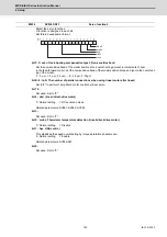
This compensates the motor torque when overshooting occurs during positioning. This is valid only when the
overshooting compensation (SV027/bitB,A) is selected.
Type 3 SV027/bitB,A=11
Set the compensation amount based on the motor stall current. Observing positioning droop waveform,
increase in increments of 1% and find the value where overshooting does not occur.
To vary compensation amount depending on the direction.
When SV042 (OVS2) is "0", change the SV031 (OVS1) value in both of the +/- directions to compensate.
To vary the compensation amount depending on the command direction, set this and SV042 (OVS2).
(SV031: + direction, SV042: - direction. However, the directions may be opposite depending on other set-
tings.)
When "-1" is set, the compensation will not be performed in the direction of the command.
Related parameters: SV027/bitB,A, SV034/bitF-C, SV042, SV082/bit2
---Setting range---
-1 to 100 (Stall current %)
Note that the range will be "-1 - 10000" (Stall current 0.01%) when SV082/bit2 is "1".
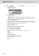
Set the unbalance torque on vertical axis and inclined axis.
When the vertical axis pull up function is enabled, the pull up compensation direction is determined by this
parameter's sign. When set to "0", and the pull up function is enabled (SV033/bitE=1), the alarm "S02 2233
Initial parameter error" occurs.
This can be used for speed loop delay compensation and collision detection function.
To use load inertia estimation function (drive monitor display), set this parameter, friction torque (SV045) and
load inertia display enabling flag(SV035/bitF).
Related parameters: SV007, SV033/bitE, SV059
---Setting range---
-100 to 100 (Stall current %)
#2231
SV031 OVS1
Overshooting compensation 1
#2232
SV032 TOF
Torque offset
Summary of Contents for MDS-E
Page 1: ......
Page 3: ......
Page 15: ......
Page 17: ......
Page 19: ......
Page 21: ......
Page 31: ......
Page 32: ...1 IB 1501229 F 1 Installation ...
Page 76: ...45 IB 1501229 F 2 Wiring and Connection ...
Page 132: ...101 IB 1501229 F 3 Safety Function ...
Page 142: ...111 IB 1501229 F 4 Setup ...
Page 277: ...MDS E EH Series Instruction Manual 4 Setup 246 IB 1501229 F ...
Page 278: ...247 IB 1501229 F 5 Servo Adjustment ...
Page 351: ...MDS E EH Series Instruction Manual 5 Servo Adjustment 320 IB 1501229 F ...
Page 352: ...321 IB 1501229 F 6 Spindle Adjustment ...
Page 404: ...373 IB 1501229 F 7 Troubleshooting ...
Page 455: ...MDS E EH Series Instruction Manual 7 Troubleshooting 424 IB 1501229 F ...
Page 456: ...425 IB 1501229 F 8 Maintenance ...
Page 475: ...MDS E EH Series Instruction Manual 8 Maintenance 444 IB 1501229 F ...
Page 476: ...445 IB 1501229 F 9 Power Backup System ...
Page 494: ...463 IB 1501229 F 10 Appx 1 Cable and Connector Assembly ...
Page 504: ...473 IB 1501229 F 11 Appx 2 D A Output Specifications for Drive Unit ...
Page 514: ...483 IB 1501229 F 12 Appx 3 Protection Function ...
Page 523: ...MDS E EH Series Instruction Manual 12 Appx 3 Protection Function 492 IB 1501229 F ...
Page 524: ...493 IB 1501229 F 13 Appx 4 Compliance to EC Directives ...
Page 528: ...497 IB 1501229 F 14 Appx 5 EMC Installation Guidelines ...
Page 540: ...509 IB 1501229 F 15 Appx 6 Higher Harmonic Suppression Measure Guidelines ...
Page 550: ......
Page 554: ......


