MDS-E/EH Series Instruction Manual
4 Setup
131
IB-1501229-F
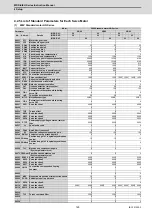
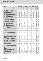
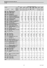
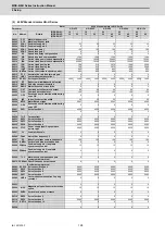
4.2.6 Servo Parameters
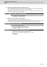
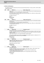
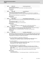
The parameters with "(PR)" requires the CNC to be turned OFF after the settings. Turn the power OFF and ON to enable
the parameter settings.
Set the gear ratio in the motor side when there is the gear between the servo motor's shaft and machine (ball
screw, etc.).
For the rotary axis, set the total deceleration (acceleration) ratio.
Even if the gear ratio is within the setting range, the electronic gears may overflow and an initial parameter
error (servo alarm 37) may occur.
For linear servo system
Set to "1".
---Setting range---
1 to 32767
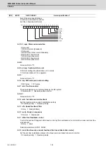
Set the gear ratio in the machine side when there is the gear between the servo motor's shaft and machine
(ball screw, etc.).
For the rotary axis, set the total deceleration (acceleration) ratio.
Even if the gear ratio is within the setting range, the electronic gears may overflow and an initial parameter
error (servo alarm 37) may occur.
For linear servo system
Set to "1".
---Setting range---
1 to 32767
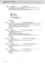
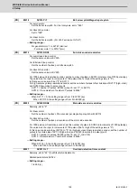
Set the position loop gain. The standard setting is "33".
The higher the setting value is, the more accurately the command can be followed, and the shorter the set-
tling time in positioning gets, however, note that a bigger shock will be applied to the machine during accel-
eration/deceleration.
When using the SHG control, also set SV004 (PGN2) and SV057 (SHGC).
When using the OMR-FF control, set the servo rigidity against quadrant projection or cutting load, etc. For
the tracking ability to the command, set by SV106(PGM).
---Setting range---
1 to 200 (rad/s)
When performing the SHG control, set the value of "SV003 x 8/3" to "SV004".
When not using the SHG control, set to "0".
When using the OMR-FF control, set to "0".
Related parameters: SV003, SV057
---Setting range---
0 to 999 (rad/s)
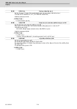
Set the speed loop gain.
The higher the setting value is, the more accurate the control will be, however, vibration tends to occur.
If vibration occurs, adjust by lowering by 20 to 30%.
The value should be determined to the 70 to 80% of the value at which the vibration stops.
The value differs depending on servo motors.
Aim at the standard value determined by the servo motor type and load inertia ratio to adjust.
---Setting range---
1 to 30000
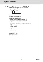
(PR)
#2201
SV001 PC1
Motor side gear ratio
(PR)
#2202
SV002 PC2
Machine side gear ratio
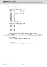
#2203
SV003 PGN1
Position loop gain 1
#2204
SV004 PGN2
Position loop gain 2
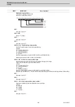
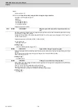
#2205
SV005 VGN1
Speed loop gain 1
Summary of Contents for MDS-E
Page 1: ......
Page 3: ......
Page 15: ......
Page 17: ......
Page 19: ......
Page 21: ......
Page 31: ......
Page 32: ...1 IB 1501229 F 1 Installation ...
Page 76: ...45 IB 1501229 F 2 Wiring and Connection ...
Page 132: ...101 IB 1501229 F 3 Safety Function ...
Page 142: ...111 IB 1501229 F 4 Setup ...
Page 277: ...MDS E EH Series Instruction Manual 4 Setup 246 IB 1501229 F ...
Page 278: ...247 IB 1501229 F 5 Servo Adjustment ...
Page 351: ...MDS E EH Series Instruction Manual 5 Servo Adjustment 320 IB 1501229 F ...
Page 352: ...321 IB 1501229 F 6 Spindle Adjustment ...
Page 404: ...373 IB 1501229 F 7 Troubleshooting ...
Page 455: ...MDS E EH Series Instruction Manual 7 Troubleshooting 424 IB 1501229 F ...
Page 456: ...425 IB 1501229 F 8 Maintenance ...
Page 475: ...MDS E EH Series Instruction Manual 8 Maintenance 444 IB 1501229 F ...
Page 476: ...445 IB 1501229 F 9 Power Backup System ...
Page 494: ...463 IB 1501229 F 10 Appx 1 Cable and Connector Assembly ...
Page 504: ...473 IB 1501229 F 11 Appx 2 D A Output Specifications for Drive Unit ...
Page 514: ...483 IB 1501229 F 12 Appx 3 Protection Function ...
Page 523: ...MDS E EH Series Instruction Manual 12 Appx 3 Protection Function 492 IB 1501229 F ...
Page 524: ...493 IB 1501229 F 13 Appx 4 Compliance to EC Directives ...
Page 528: ...497 IB 1501229 F 14 Appx 5 EMC Installation Guidelines ...
Page 540: ...509 IB 1501229 F 15 Appx 6 Higher Harmonic Suppression Measure Guidelines ...
Page 550: ......
Page 554: ......

