

MDS-E/EH Series Instruction Manual
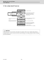
5 Servo Adjustment
257
IB-1501229-F
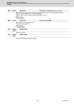
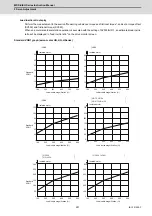
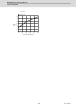
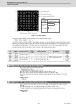
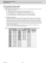
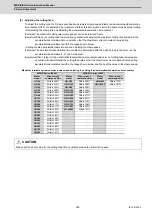
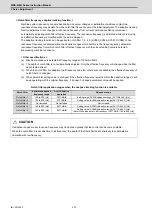
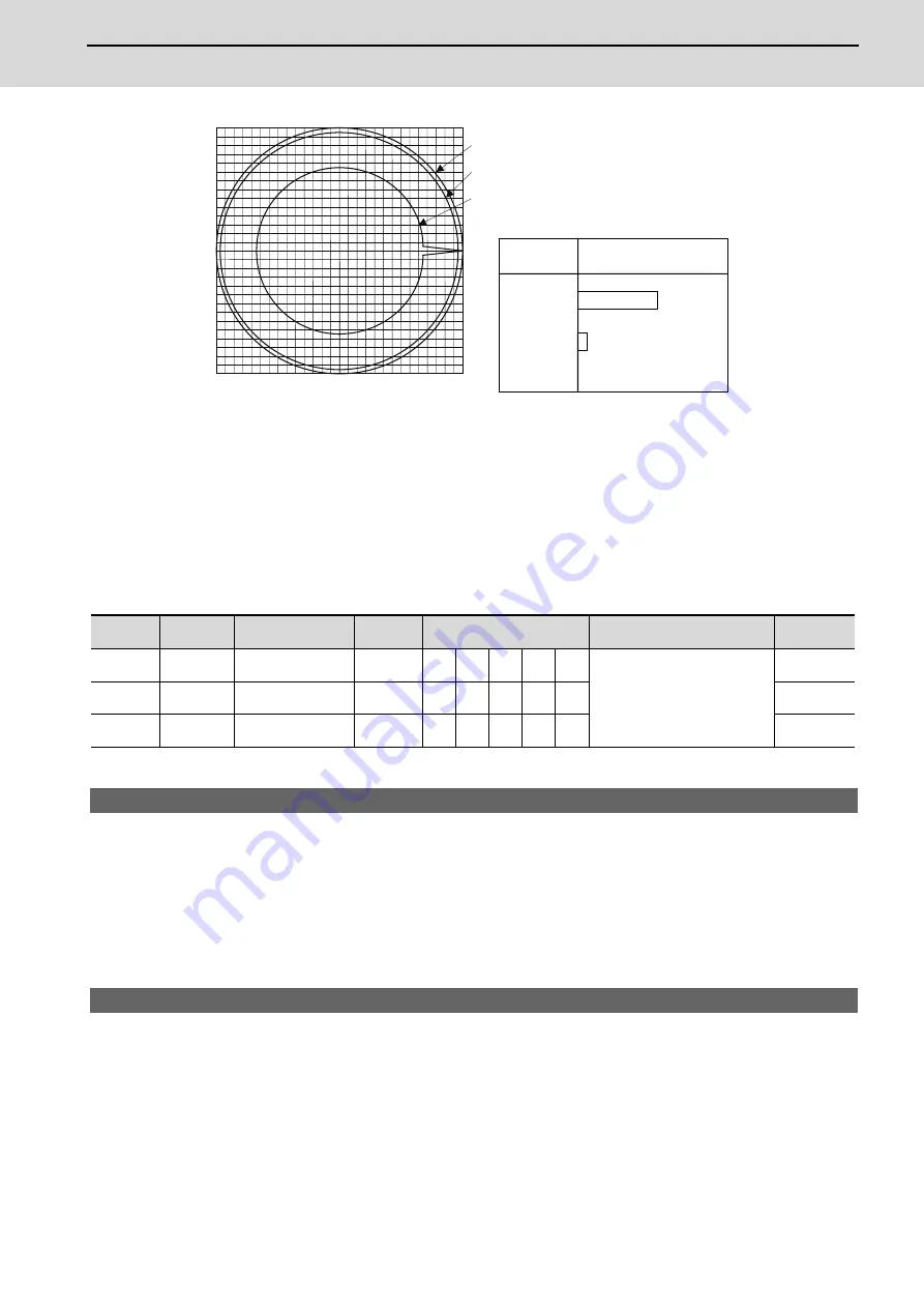
Shape error characteristics
During SHG control, PGN1, PGN2 and SHGC are set with the following ratio.
PGN1 : PGN2 : SHGC = 1 : 8/3 : 6
During SHG control even if the PGN1 setting value is the same, the actual position loop gain will be higher, so the
speed loop must have a sufficient response. If the speed loop response is low, vibration or overshooting could occur
during acceleration/deceleration in the same manner as conventional control. If the speed loop gain has been
lowered because machine resonance occurs, lower the position loop gain and adjust.
【
#2208
】
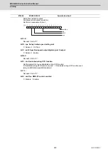
SV008 VIA Speed loop lead compensation
Set the gain of the speed loop integral control.
Standard setting: 1364
Standard setting in the SHG control: 1900
Adjust the value by increasing/decreasing this by about 100 at a time.
Raise this value to improve contour tracking accuracy in high-speed cutting.
Lower this value when the position droop does not stabilize (when the vibration of 10 to 20Hz
occurs).
---Setting range---
1 to 9999
【
#2215
】
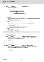
SV015 FFC Acceleration rate feed forward gain
When a relative error in synchronous control is too large, set this parameter to the axis that is
delaying.
The standard setting is "0". The standard setting in the SHG control is "100".
To adjust a relative error in acceleration/deceleration, increase the value by 50 at a time.
---Setting range---
0 to 999 (%)
No.
Abbrev.
Parameter name
Setting
ratio
Setting example
Explanation
Setting
range
SV003
(SV049)
PGN1
(PGN1sp)
Position loop gain 1
1
21
27
33
39
48
Always set with a combination
of these three parameters.
1 to 200
(rad/s)
SV004
(SV050)
PGN2
(PGN2sp)
Position loop gain 2
8/3
56
72
88
104 128
0 to 999
(rad/s)
SV057
(SV058)
SHGC
(SHGCsp)
SHG control gain
6
126 162 198 234 288
0 to 1200
(rad/s)
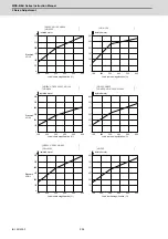
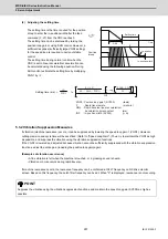
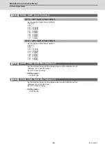
(F=3000mm/min ,
ERROR=5.0μm/div )
-50.0
50.0
0.0
0.0
-50.0
50.0
[1] : Commanded path
[2] : SHG control (PGN1=47)
[3] : Conventional control (PGN1=33)
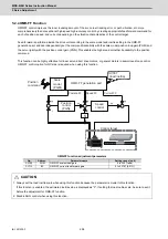
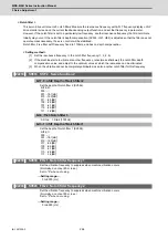
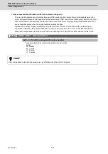
Conventional
control
SHG control
Control
method
Roundness error (
ȣ
m)
2.5
22.5
<Effect>
Summary of Contents for MDS-E
Page 1: ......
Page 3: ......
Page 15: ......
Page 17: ......
Page 19: ......
Page 21: ......
Page 31: ......
Page 32: ...1 IB 1501229 F 1 Installation ...
Page 76: ...45 IB 1501229 F 2 Wiring and Connection ...
Page 132: ...101 IB 1501229 F 3 Safety Function ...
Page 142: ...111 IB 1501229 F 4 Setup ...
Page 277: ...MDS E EH Series Instruction Manual 4 Setup 246 IB 1501229 F ...
Page 278: ...247 IB 1501229 F 5 Servo Adjustment ...
Page 351: ...MDS E EH Series Instruction Manual 5 Servo Adjustment 320 IB 1501229 F ...
Page 352: ...321 IB 1501229 F 6 Spindle Adjustment ...
Page 404: ...373 IB 1501229 F 7 Troubleshooting ...
Page 455: ...MDS E EH Series Instruction Manual 7 Troubleshooting 424 IB 1501229 F ...
Page 456: ...425 IB 1501229 F 8 Maintenance ...
Page 475: ...MDS E EH Series Instruction Manual 8 Maintenance 444 IB 1501229 F ...
Page 476: ...445 IB 1501229 F 9 Power Backup System ...
Page 494: ...463 IB 1501229 F 10 Appx 1 Cable and Connector Assembly ...
Page 504: ...473 IB 1501229 F 11 Appx 2 D A Output Specifications for Drive Unit ...
Page 514: ...483 IB 1501229 F 12 Appx 3 Protection Function ...
Page 523: ...MDS E EH Series Instruction Manual 12 Appx 3 Protection Function 492 IB 1501229 F ...
Page 524: ...493 IB 1501229 F 13 Appx 4 Compliance to EC Directives ...
Page 528: ...497 IB 1501229 F 14 Appx 5 EMC Installation Guidelines ...
Page 540: ...509 IB 1501229 F 15 Appx 6 Higher Harmonic Suppression Measure Guidelines ...
Page 550: ......
Page 554: ......


