

MDS-E/EH Series Instruction Manual
3 Safety Function
107
IB-1501229-F
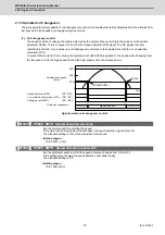
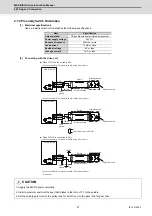
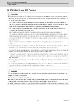
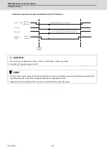
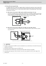
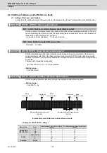
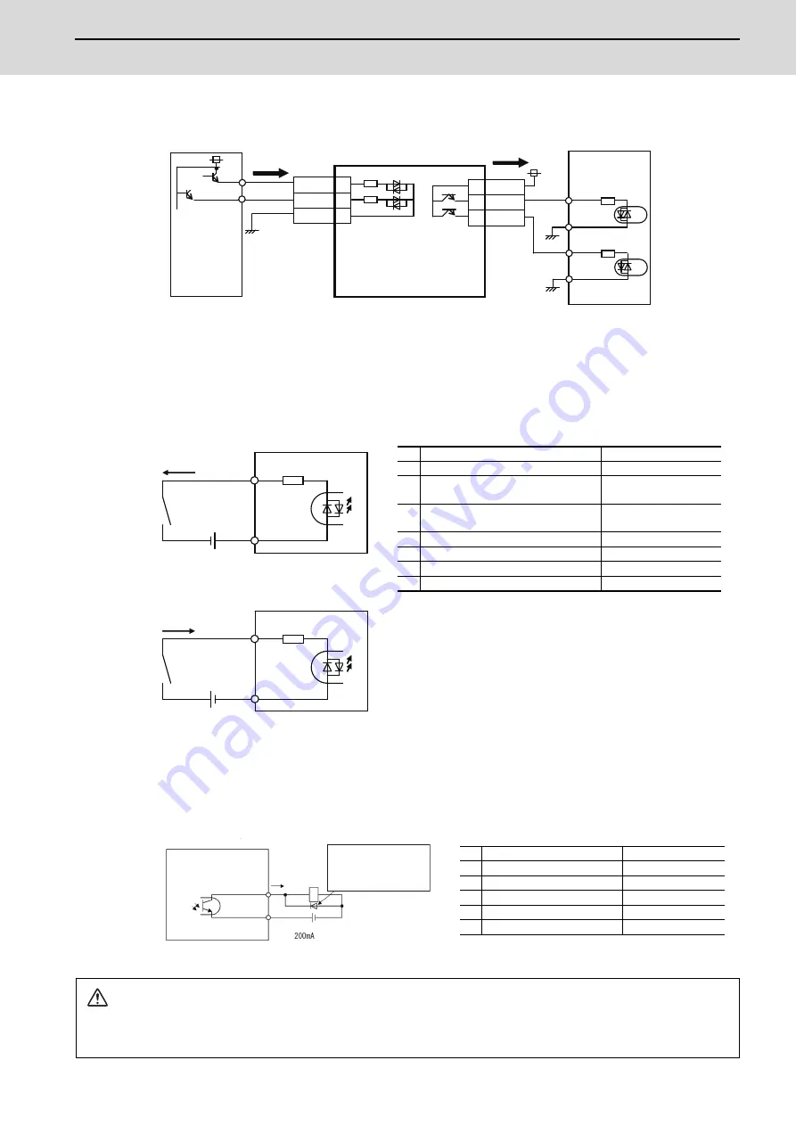
External input/output signal connection example when using a NC controller
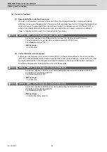
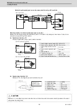
Detail description of external input/output signal connection
Details of the input/output signal as stated before (refer to "I/O class" in the table) are shown below. Connect to an
external device by referring to this section.
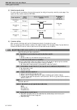
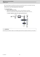
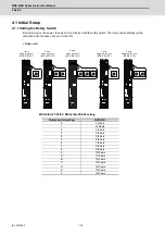
(a) Digital input interface: DI
Provide a signal with a relay or open-collector transistor.
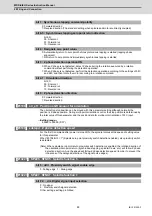
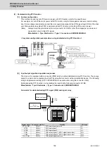
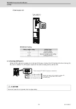
(b) Digital output interface: DO
Maximum 1.3V of voltage drop occurs inside the drive unit.
1
Input voltage at external contact ON 24VDC±10%
2
Input current at external contact ON 10mA or more
3
Input voltage at external contact
OFF
4V or less
4
Input current at external contact
OFF
2mA or less
5
Input resistance
4k
Ω
6
Tolerable chattering time
1ms or less
7
Input signal holding time
600ms or more
8
Input circuit operation delay time
10ms typ 30ms or less
1
Insulation method
Insulation
2
Rated load voltage
24V
3
Rated current
40mA or less
4
Maximum current
50mA or less
5
Rush current
100mA or less
6
Internal voltage drop
1.3V or less
CAUTION
Maximum 1.3V of voltage drop occurs inside the drive unit. Select an external connection device operable in the output
voltage after the voltage drop.
STO1
4
STO_COM
3
STO2
5
TOF_COM
TOF1
8
6
TOF2
7
Door signal contact
Drive unit
Shutoff
command
Shutoff
effect
IO unit
for NC controller
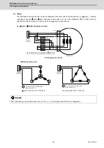
STO_COM
STO1/STO2
4kΩ
䊄䊤䉟䊑䊡䊆䉾䊃
± 10%
200mA
䊄䊤䉟䊑䊡䊆䉾䊃
± 10%
200mA
STO_COM
STO1/STO2
4kΩ
24VDC
Drive unit
Switch
24VDC
[1] Sink input/output interface
[2] Source input/output interface
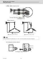
Switch
Drive unit
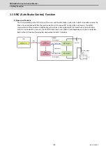
TOF1/TOF2
T
OF_COM
Drive unit
The drive unit is
damaged when the
polarity is reversed.
(Note) 24VDC±10%
Load
Summary of Contents for MDS-E
Page 1: ......
Page 3: ......
Page 15: ......
Page 17: ......
Page 19: ......
Page 21: ......
Page 31: ......
Page 32: ...1 IB 1501229 F 1 Installation ...
Page 76: ...45 IB 1501229 F 2 Wiring and Connection ...
Page 132: ...101 IB 1501229 F 3 Safety Function ...
Page 142: ...111 IB 1501229 F 4 Setup ...
Page 277: ...MDS E EH Series Instruction Manual 4 Setup 246 IB 1501229 F ...
Page 278: ...247 IB 1501229 F 5 Servo Adjustment ...
Page 351: ...MDS E EH Series Instruction Manual 5 Servo Adjustment 320 IB 1501229 F ...
Page 352: ...321 IB 1501229 F 6 Spindle Adjustment ...
Page 404: ...373 IB 1501229 F 7 Troubleshooting ...
Page 455: ...MDS E EH Series Instruction Manual 7 Troubleshooting 424 IB 1501229 F ...
Page 456: ...425 IB 1501229 F 8 Maintenance ...
Page 475: ...MDS E EH Series Instruction Manual 8 Maintenance 444 IB 1501229 F ...
Page 476: ...445 IB 1501229 F 9 Power Backup System ...
Page 494: ...463 IB 1501229 F 10 Appx 1 Cable and Connector Assembly ...
Page 504: ...473 IB 1501229 F 11 Appx 2 D A Output Specifications for Drive Unit ...
Page 514: ...483 IB 1501229 F 12 Appx 3 Protection Function ...
Page 523: ...MDS E EH Series Instruction Manual 12 Appx 3 Protection Function 492 IB 1501229 F ...
Page 524: ...493 IB 1501229 F 13 Appx 4 Compliance to EC Directives ...
Page 528: ...497 IB 1501229 F 14 Appx 5 EMC Installation Guidelines ...
Page 540: ...509 IB 1501229 F 15 Appx 6 Higher Harmonic Suppression Measure Guidelines ...
Page 550: ......
Page 554: ......


