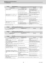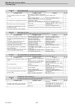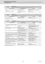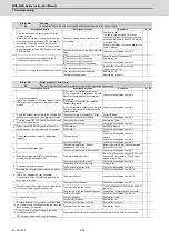
MDS-E/EH Series Instruction Manual
7 Troubleshooting
411
IB-1501229-F
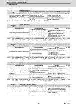
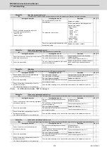
Alarm No.
73
Power supply: Over regeneration
Over-regeneration detection level became over 100%. The regenerative resistor is overloaded. This alarm cannot be reset for 15
min from the occurrence. Leave the drive system energized for more than 15 min, then turn the power ON to reset the alarm.
Investigation details
Investigation results
Remedies
CV
1
Check the alarm occurrence state and regenerative
load displayed on the NC Monitor screen while
changing the operation mode.
The regenerative load value increases when
the power is turned ON and the motor is not
rotated.
Check whether the state is affected by power
fluctuation, grounding or noise. If there is no
problem, replace the unit.
◯
The regenerative load value increases each
time the motor decelerates, and the alarm
occurs.
A-CR:
Check the investigation item No. 2.
C1-CV:
Check the investigation item No. 4.
The regenerative load value increases each
time the motor decelerates, but the alarm
does not occur when the operation mode is
eased.
A-CR:
Check the investigation item No. 2.
C1-CV:
Ease the operation mode.
2
Check whether the parameter (regenerative
resistor type) of the drive unit controlling the power
supply unit is correct.
The setting is incorrect.
Correctly set. (Check the alarm No. "6D"
items.)
◯
The setting is correct.
Check the investigation item No. 3.
3
Check the regenerative resistor's state.
[1] Is oil adhered?
[2] Measure the resistance value.
The regenerative resistor is abnormal.
Replace the regenerative resistor.
◯
There is no problem.
Check the investigation item No. 4.
4
Check the alarm No. "75" items.
◯
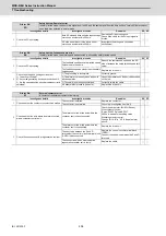
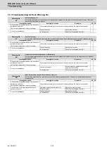
Alarm No.
74
Power supply option unit error:
An alarm was detected in the power backup unit (an option unit for the power supply).
Investigation details
Investigation results
Remedies
SV SP
1
Check the LED display on the power backup unit.
Check the LED display on the power backup
unit to identify what alarm is occurring to the
unit.
Fix the error occurring to the power backup
unit and remove the alarm.
Refer to MDS-E/EH Series Instruction
Manual (IB-1501229(ENG)) "List of power
backup function alarms".
◯
◯
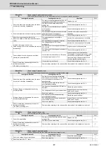
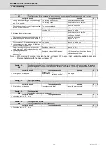
Alarm No.
75
Power supply: Overvoltage
L+ and L- bus voltage in main circuit exceeded the allowable value. As the voltage between L+ and L- is high immediately after
this alarm, another alarm may occur if this alarm is reset in a short time. Wait more than 5 min before resetting so that the voltage
drops.
Investigation details
Investigation results
Remedies
CV
1
Check the repeatability.
The alarm occurs each time the motor
decelerates.
Check the investigation item No. 3.
◯
The alarm occurs occasionally.
Check the investigation item No. 2.
2
Check the power supply's alarm history.
Auxiliary regeneration frequency over (E8)
occurs just before the over-voltage occurs.
Limit the occurrence of the excessive
instantaneous regeneration by not
decelerating multiple axes at the same time.
◯
Others.
Check the investigation item No. 3.
3
Check the power capacity.
The power capacity is insufficient.
Increase the power capacity.
◯
The specified power capacity is secured.
Check the investigation item No. 4.
4
Measure the voltage across wires.
[1] Is the voltage 170V or more even when the
motor is accelerating?
The voltage drops to 170V or less
occasionally.
Increase the power capacity.
◯
The difference of the voltage across wires is
10V or more.
Improve the power phase balance.
The difference of the voltage across wires is
less than 10V.
Check the investigation item No. 5.
5
Measure the power voltage with a synchroscope,
and check whether there is any distortion.
[1] Are there any other devices causing the power
distortion?
The power voltage is distorted.
Improve the source of the distortion.
Install an AC reactor.
◯
The power voltage waveform is not
abnormal.
Check the investigation item No. 6.
6
Check if there is any abnormality in the unit's
ambient environment.
(Ex. Noise, grounding, etc.)
Take remedies according to the causes of the abnormality in the ambient environment.
◯
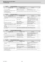
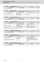
Alarm No.
76
Power supply: Function setting error
The rotary switch setting of external emergency stop is not correct, or a wrong external emergency stop signal is input.
Investigation details
Investigation results
Remedies
CV
1
Check the rotary switch setting.
When using external emergency stop, rotary
switch is not set to "4".
Set the rotary switch to "4".
◯
2
Check if there is any abnormality in the unit's
ambient environment.
No abnormality is found in particular.
Replace the drive unit.
◯
The grounding is incomplete.
Take remedies according to the causes of
the abnormality.
Additionally ground and review.
Summary of Contents for MDS-E
Page 1: ......
Page 3: ......
Page 15: ......
Page 17: ......
Page 19: ......
Page 21: ......
Page 31: ......
Page 32: ...1 IB 1501229 F 1 Installation ...
Page 76: ...45 IB 1501229 F 2 Wiring and Connection ...
Page 132: ...101 IB 1501229 F 3 Safety Function ...
Page 142: ...111 IB 1501229 F 4 Setup ...
Page 277: ...MDS E EH Series Instruction Manual 4 Setup 246 IB 1501229 F ...
Page 278: ...247 IB 1501229 F 5 Servo Adjustment ...
Page 351: ...MDS E EH Series Instruction Manual 5 Servo Adjustment 320 IB 1501229 F ...
Page 352: ...321 IB 1501229 F 6 Spindle Adjustment ...
Page 404: ...373 IB 1501229 F 7 Troubleshooting ...
Page 455: ...MDS E EH Series Instruction Manual 7 Troubleshooting 424 IB 1501229 F ...
Page 456: ...425 IB 1501229 F 8 Maintenance ...
Page 475: ...MDS E EH Series Instruction Manual 8 Maintenance 444 IB 1501229 F ...
Page 476: ...445 IB 1501229 F 9 Power Backup System ...
Page 494: ...463 IB 1501229 F 10 Appx 1 Cable and Connector Assembly ...
Page 504: ...473 IB 1501229 F 11 Appx 2 D A Output Specifications for Drive Unit ...
Page 514: ...483 IB 1501229 F 12 Appx 3 Protection Function ...
Page 523: ...MDS E EH Series Instruction Manual 12 Appx 3 Protection Function 492 IB 1501229 F ...
Page 524: ...493 IB 1501229 F 13 Appx 4 Compliance to EC Directives ...
Page 528: ...497 IB 1501229 F 14 Appx 5 EMC Installation Guidelines ...
Page 540: ...509 IB 1501229 F 15 Appx 6 Higher Harmonic Suppression Measure Guidelines ...
Page 550: ......
Page 554: ......

