


MDS-E/EH Series Instruction Manual
11 Appx. 2: D/A Output Specifications for Drive Unit
481
IB-1501229-F
11.3.2 Spindle Drive Unit Settings
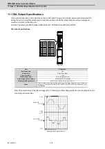
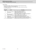
Internal data output (Data No. -1 to 3, 50, 60, 127)
Set when outputting data other than in standard magnification (the magnification is 1). When "0" is set, the
magnification will be 1, which is the same as when "100" is set.
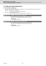
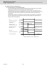
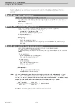
(Example 1) When SP125=1, SP127=50
Commanded motor rotation speed is output to D/A output channel 1 in increments of 2000r/min/V.
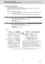
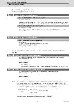
(Example 2) When SP126=2, SP128=200
The torque axis current command is output to D/A output channel 2 in increments of 50%/V.
【
#13127
】
SP127 DA1MPY D/A output ch1 output scale
Set the output scale in increments of 1/100.
When "0" is set, the scale is the same as when "100" is set.
---Setting range---
-32768 to 32767 (1/100-fold)
【
#13128
】
SP128 DA2MPY D/A output ch2 output scale
Set the output scale in increments of 1/100.
When "0" is set, the scale is the same as when "100" is set.
---Setting range---
-32768 to 32767 (1/100-fold)
+2.5
+2.5 [V]
+5 [V]
0 [V]
+4.0
+1.0
+1. 5
- 1. 5
2000r/min/V
50%/V
SP125=0
SP127=50
SP126=2
SP128=200
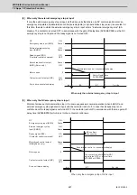
+3. 6
+1. 7
+1. 3
- 1. 2
0 [V]
+1.1
- 0. 8
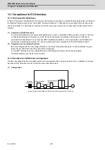
SP125=0
SP127=100
+2. 5
+0. 5
- 2. 5
- 0.5
1000r/min/V
+2.5 [V]
0 [V]
+5 [V]
(acceleration)
55%
3000r/min (reverse run)
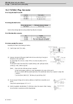
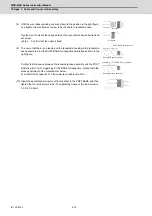
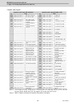
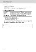
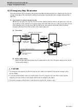
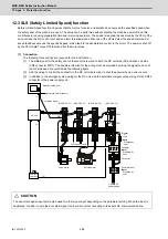
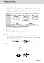
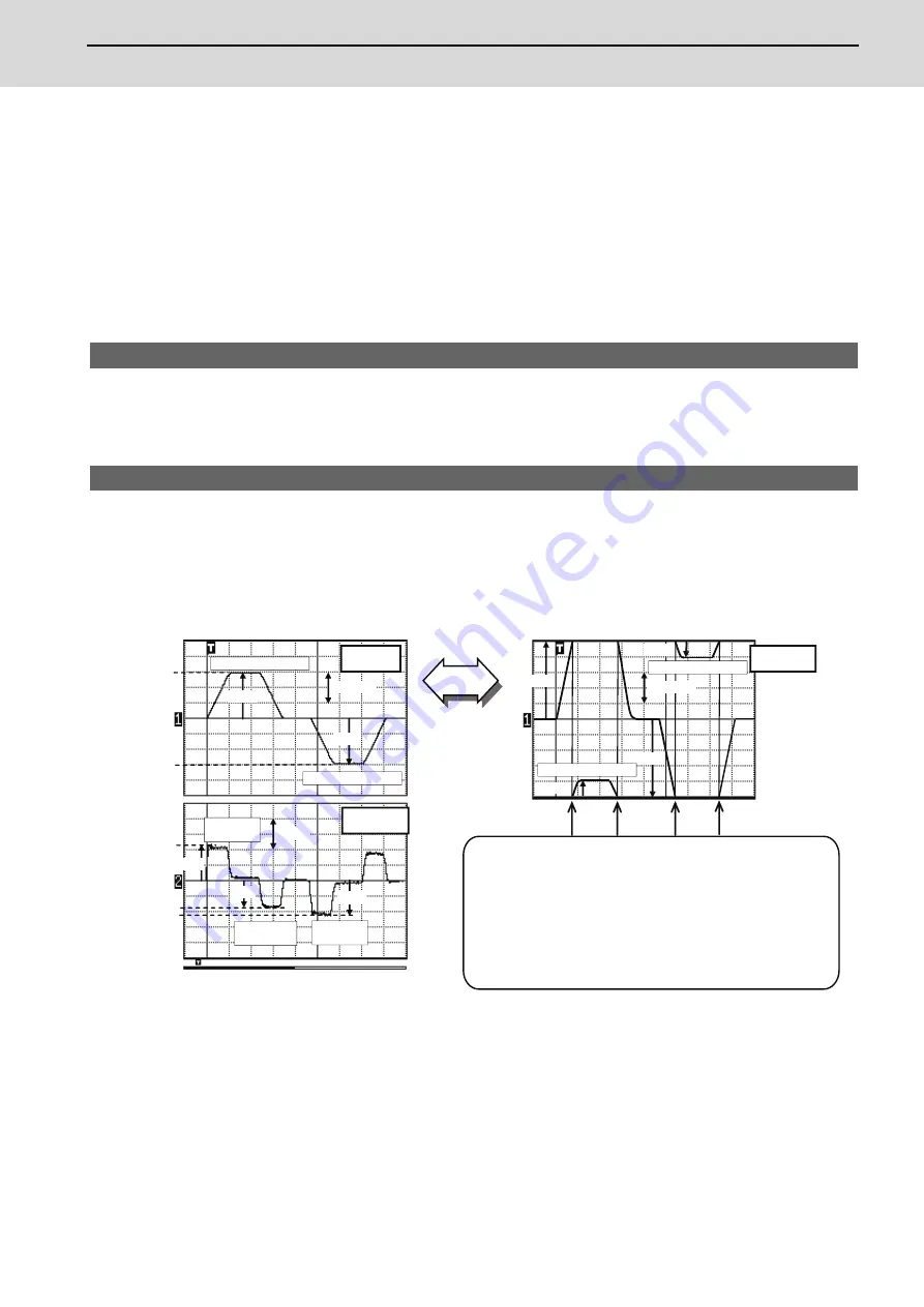
Example of D/A output waveform: 3000r/min during acceleration and deceleration
《
Speed FB
》
《
Current FB
》
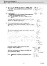
< When 3000r/min is displayed at the setting range of “1000r/min/V” >
When the speed waveform at 3000r/min is measured using a
high-speed waveform recorder with SP127 set to “100”, the data
exceeds the D/A output range (+5.0V for forward run and 0V for
reverse run) at 2500r/min, but it will be cleared immediately and then
the remaining data will be output. Even if the data exceeds the D/A
output range more than one time, it will be cleared and the remains
will be output.
Magnification
change
3000r/min (forward run)
3000r/min (reverse run)
3000r/min (forward run)
(deceleration)
40%
(acceleration)
60%
Summary of Contents for MDS-E
Page 1: ......
Page 3: ......
Page 15: ......
Page 17: ......
Page 19: ......
Page 21: ......
Page 31: ......
Page 32: ...1 IB 1501229 F 1 Installation ...
Page 76: ...45 IB 1501229 F 2 Wiring and Connection ...
Page 132: ...101 IB 1501229 F 3 Safety Function ...
Page 142: ...111 IB 1501229 F 4 Setup ...
Page 277: ...MDS E EH Series Instruction Manual 4 Setup 246 IB 1501229 F ...
Page 278: ...247 IB 1501229 F 5 Servo Adjustment ...
Page 351: ...MDS E EH Series Instruction Manual 5 Servo Adjustment 320 IB 1501229 F ...
Page 352: ...321 IB 1501229 F 6 Spindle Adjustment ...
Page 404: ...373 IB 1501229 F 7 Troubleshooting ...
Page 455: ...MDS E EH Series Instruction Manual 7 Troubleshooting 424 IB 1501229 F ...
Page 456: ...425 IB 1501229 F 8 Maintenance ...
Page 475: ...MDS E EH Series Instruction Manual 8 Maintenance 444 IB 1501229 F ...
Page 476: ...445 IB 1501229 F 9 Power Backup System ...
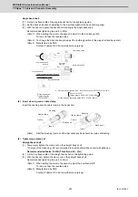
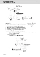
Page 494: ...463 IB 1501229 F 10 Appx 1 Cable and Connector Assembly ...
Page 504: ...473 IB 1501229 F 11 Appx 2 D A Output Specifications for Drive Unit ...
Page 514: ...483 IB 1501229 F 12 Appx 3 Protection Function ...
Page 523: ...MDS E EH Series Instruction Manual 12 Appx 3 Protection Function 492 IB 1501229 F ...
Page 524: ...493 IB 1501229 F 13 Appx 4 Compliance to EC Directives ...
Page 528: ...497 IB 1501229 F 14 Appx 5 EMC Installation Guidelines ...
Page 540: ...509 IB 1501229 F 15 Appx 6 Higher Harmonic Suppression Measure Guidelines ...
Page 550: ......
Page 554: ......


