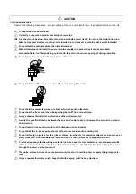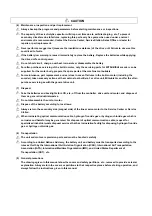
Store and use the units under the following environment conditions.
(Note) For details, confirm each unit or motor specifications in addition.
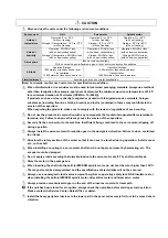
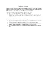
When disinfectants or insecticides must be used to treat wood packaging materials, always use methods
other than fumigation (for example, apply heat treatment at the minimum wood core temperature of 56 °C
for a minimum duration of 30 minutes (ISPM No. 15 (2009))).
If products such as units are directly fumigated or packed with fumigated wooden materials, halogen
substances (including fluorine, chlorine, bromine and iodine) contained in fumes may contribute to the
erosion of the capacitors.
When exporting the products, make sure to comply with the laws and regulations of each country.
Do not use the products in conjunction with any components that contain halogenated flame retardants
(bromine, etc). Failure to observe this may cause the erosion of the capacitors.
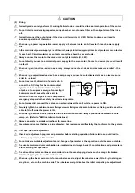
Securely fix the servo motor to the machine. Insufficient fixing could lead to the servo motor slipping off
during operation.
Always install the servo motor with reduction gear in the designated direction. Failure to do so could lead
to oil leaks.
Structure the rotary sections of the motor so that it can never be touched during operation. Install a cover,
etc., on the shaft.
When installing a coupling to a servo motor shaft end, do not apply an impact by hammering, etc. The
encoder could be damaged.
Do not apply a load exceeding the tolerable load onto the servo motor shaft. The shaft could break.
Store the motor in the package box.
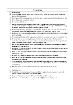
When inserting the shaft into the built-in IPM/SPM spindle motor, do not heat the rotor higher than 130°C.
The magnet could be demagnetized, and the specifications characteristics will not be ensured.
Always use a nonmagnetic tool (explosion-proof beryllium copper alloy safety tool: NGK Insulators, etc.)
when installing the built-in IPM/SPM spindle motor, direct-drive motor and linear servo motor.
Always provide a mechanical stopper on the end of the linear servo motor's travel path.
If the unit has been stored for a long time, always check the operation before starting actual operation.
Please contact the Service Center, Sales Office or dealer.
Install the heavy peripheral devices to the lower part in the panel and securely fix it not to be moved due to
vibration.
CAUTION
Environment
Unit
Servo motor
Spindle motor
Ambient
temperature
Operation: 0 to +55°C
(with no freezing),
Storage / Transportation: -15°C to +70°C
(with no freezing)
Operation: 0 to +40°C
(with no freezing),
Storage: -15°C to +70°C
(with no freezing)
Operation: 0 to +40°C
(with no freezing),
Storage: -20°C to +65°C
(with no freezing)
Ambient
humidity
Operation: 90%RH or less
(with no dew condensation)
Storage / Transportation: 90%RH or less
(with no dew condensation)
Operation: 80%RH or less
(with no dew condensation),
Storage: 90%RH or less
(with no dew condensation)
Operation: 90%RH or less
(with no dew condensation)
Storage: 90%RH or less
(with no dew condensation)
Atmosphere
Indoors (no direct sunlight)
With no corrosive gas, inflammable gas, oil mist, dust or conductive fine particles
Altitude
Operation/Storage:
1000 meters or less above sea level,
Transportation:
13000 meters or less above sea level
Operation/Storage:
1000 meters or less above sea level,
Transportation:
10000 meters or less above sea level
Vibration/impact
According to each unit or motor specification
Summary of Contents for MDS-E
Page 1: ......
Page 3: ......
Page 15: ......
Page 17: ......
Page 19: ......
Page 21: ......
Page 31: ......
Page 32: ...1 IB 1501229 F 1 Installation ...
Page 76: ...45 IB 1501229 F 2 Wiring and Connection ...
Page 132: ...101 IB 1501229 F 3 Safety Function ...
Page 142: ...111 IB 1501229 F 4 Setup ...
Page 277: ...MDS E EH Series Instruction Manual 4 Setup 246 IB 1501229 F ...
Page 278: ...247 IB 1501229 F 5 Servo Adjustment ...
Page 351: ...MDS E EH Series Instruction Manual 5 Servo Adjustment 320 IB 1501229 F ...
Page 352: ...321 IB 1501229 F 6 Spindle Adjustment ...
Page 404: ...373 IB 1501229 F 7 Troubleshooting ...
Page 455: ...MDS E EH Series Instruction Manual 7 Troubleshooting 424 IB 1501229 F ...
Page 456: ...425 IB 1501229 F 8 Maintenance ...
Page 475: ...MDS E EH Series Instruction Manual 8 Maintenance 444 IB 1501229 F ...
Page 476: ...445 IB 1501229 F 9 Power Backup System ...
Page 494: ...463 IB 1501229 F 10 Appx 1 Cable and Connector Assembly ...
Page 504: ...473 IB 1501229 F 11 Appx 2 D A Output Specifications for Drive Unit ...
Page 514: ...483 IB 1501229 F 12 Appx 3 Protection Function ...
Page 523: ...MDS E EH Series Instruction Manual 12 Appx 3 Protection Function 492 IB 1501229 F ...
Page 524: ...493 IB 1501229 F 13 Appx 4 Compliance to EC Directives ...
Page 528: ...497 IB 1501229 F 14 Appx 5 EMC Installation Guidelines ...
Page 540: ...509 IB 1501229 F 15 Appx 6 Higher Harmonic Suppression Measure Guidelines ...
Page 550: ......
Page 554: ......


