


MDS-E/EH Series Instruction Manual
1 Installation
4
IB-1501229-F
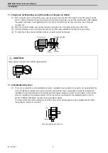
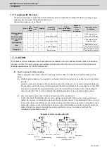
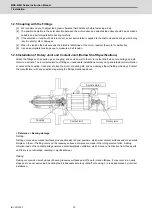
1.1.3 Cautions for Mounting Load (Prevention of Impact on Shaft)
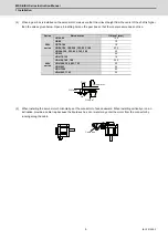
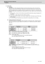
[1] When using the servo motor with key way, use the screw hole at the end of the shaft to mount the pulley onto the
shaft. To install, first place the double-end stud into the shaft screw holes, contact the coupling end surface against
the washer, and press in as if tightening with a nut. When the shaft does not have a key way, use a frictional
coupling, etc.
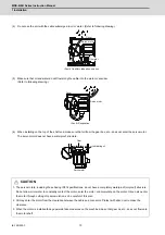
[2] When removing the pulley, use a pulley remover, and make sure not to apply an impact on the shaft.
[3] Install a protective cover on the rotary sections such as the pulley installed on the shaft to ensure safety.
[4] The direction of the encoder installed on the servo motor cannot be changed.
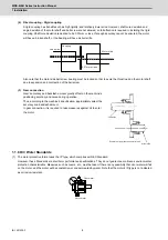
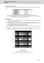
1.1.4 Installation Direction
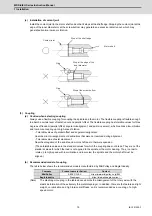
[1] There are no restrictions on the installation direction. Installation in any direction is possible, but as a standard the
motor is installed so that the motor power line and encoder cable cannon plugs (lead-in wires) face downward.
Installation in the standard direction is effective against dripping. Measure to prevent oil and water must be taken
when not installing in the standard direction. When the motor is not installed in the standard direction, refer to
section "Oil/Water Standards" and take the appropriate measures.
The brake plates may make a sliding sound when a servo motor with magnetic brake is installed with the shaft
facing upward, but this is not a fault.
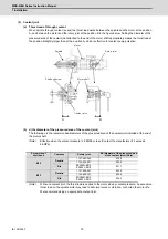
CAUTION
Never hammer the end of the shaft during assembly.
Servo motor
Double-end stud
Nut
Pulley
Washer
Up
Down
Standard installation direction
Summary of Contents for MDS-E
Page 1: ......
Page 3: ......
Page 15: ......
Page 17: ......
Page 19: ......
Page 21: ......
Page 31: ......
Page 32: ...1 IB 1501229 F 1 Installation ...
Page 76: ...45 IB 1501229 F 2 Wiring and Connection ...
Page 132: ...101 IB 1501229 F 3 Safety Function ...
Page 142: ...111 IB 1501229 F 4 Setup ...
Page 277: ...MDS E EH Series Instruction Manual 4 Setup 246 IB 1501229 F ...
Page 278: ...247 IB 1501229 F 5 Servo Adjustment ...
Page 351: ...MDS E EH Series Instruction Manual 5 Servo Adjustment 320 IB 1501229 F ...
Page 352: ...321 IB 1501229 F 6 Spindle Adjustment ...
Page 404: ...373 IB 1501229 F 7 Troubleshooting ...
Page 455: ...MDS E EH Series Instruction Manual 7 Troubleshooting 424 IB 1501229 F ...
Page 456: ...425 IB 1501229 F 8 Maintenance ...
Page 475: ...MDS E EH Series Instruction Manual 8 Maintenance 444 IB 1501229 F ...
Page 476: ...445 IB 1501229 F 9 Power Backup System ...
Page 494: ...463 IB 1501229 F 10 Appx 1 Cable and Connector Assembly ...
Page 504: ...473 IB 1501229 F 11 Appx 2 D A Output Specifications for Drive Unit ...
Page 514: ...483 IB 1501229 F 12 Appx 3 Protection Function ...
Page 523: ...MDS E EH Series Instruction Manual 12 Appx 3 Protection Function 492 IB 1501229 F ...
Page 524: ...493 IB 1501229 F 13 Appx 4 Compliance to EC Directives ...
Page 528: ...497 IB 1501229 F 14 Appx 5 EMC Installation Guidelines ...
Page 540: ...509 IB 1501229 F 15 Appx 6 Higher Harmonic Suppression Measure Guidelines ...
Page 550: ......
Page 554: ......


