


MDS-E/EH Series Instruction Manual
14 Appx. 5: EMC Installation Guidelines
499
IB-1501229-F
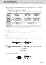
14.3 EMC Measures
The main items relating to EMC measures include the following.
[1] Store the device in an electrically sealed metal panel.
[2] Earth all conductors that are floating electrically. (Lower the impedance.)
[3] Wire the power line separated from the signal wire as far as possible.
[4] Use shielded wires for the cables wired outside of the panel.
[5] Install a noise filter.
Ensure the following items to suppress noise radiated outside of the panel.
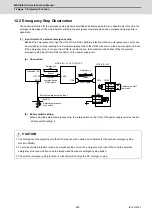
[1] Accurately ground the devices.
[2] Clamp shielded wires in the control panel.
[3] Increase the panel's electrical seal. Reduce the gap and hole size.
Note that the electromagnetic noise radiated in the air is greatly affected by the clearance of the panel and the
quality of the cable shield.
14.4 Measures for Panel Structure
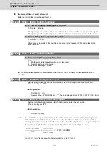
The design of the panel is a very important factor for the EMC measures, so take the following measures into consideration.
14.4.1 Measures for Control Panel Unit
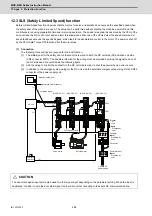
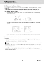
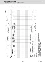
[1] Use metal for all materials configuring the panel.
[2] For the joining of the top plate and side plates, etc., mask the contact surface with paint, and fix with welding or
screws so that the impedance is reduced. In either case, keep the joining clearance to a max. of 20cm for a better
effect.
Note that if the plate warps due to the screw fixing, etc., creating a clearance, noise could leak from that place.
[3] Plate the earth plate (with nickel, tin), and connect the connections with a low impedance.
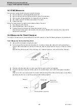
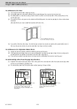
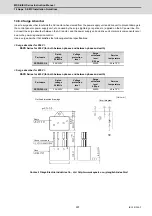
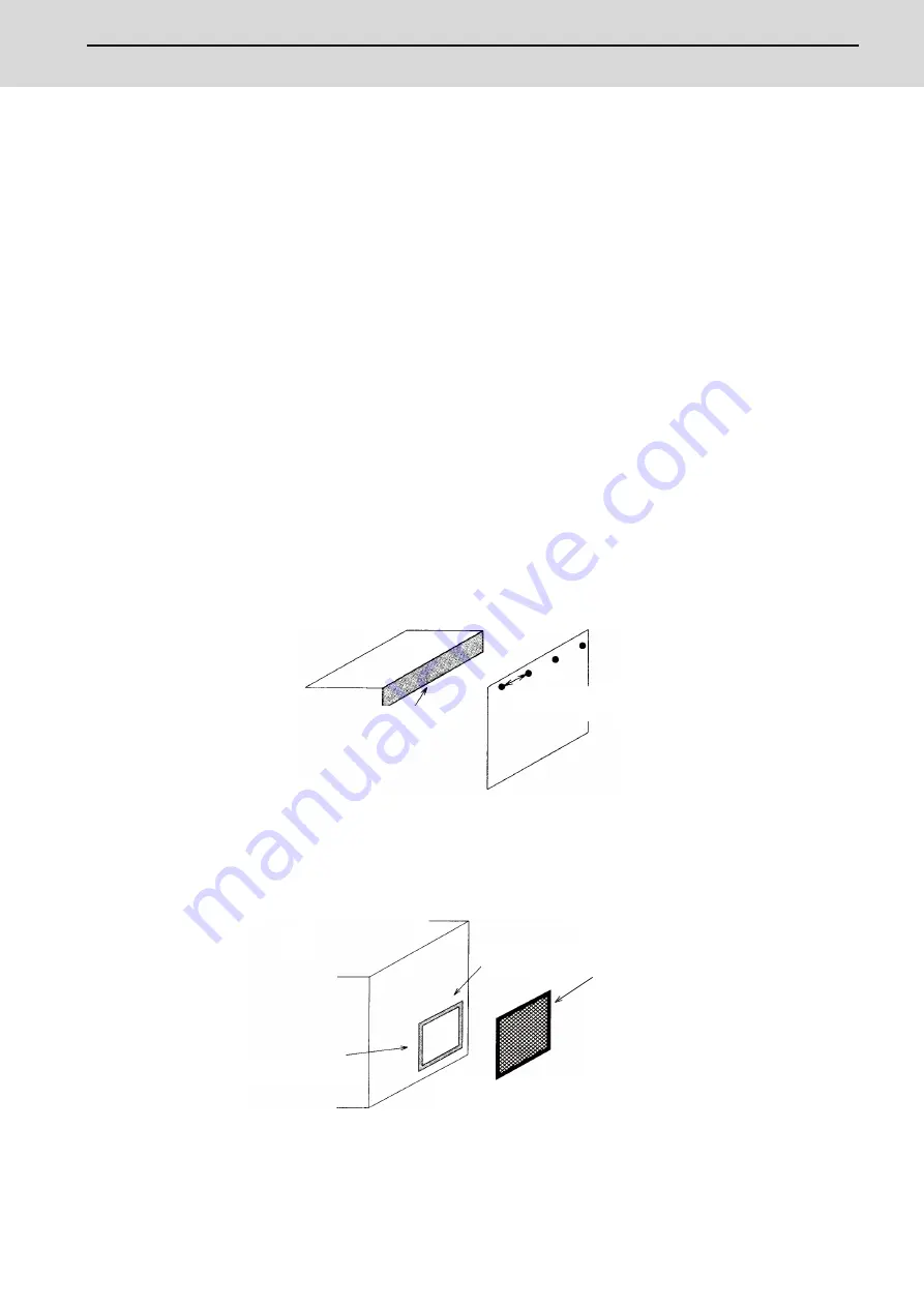
[4] If there is a opening on the panel surface, such as the ventilation holes, cover it with a metal plate or expanded
metal.
Make sure not to connect using metal or a conductor without peeling off the surface, which results in an insufficient
electrical connection. (ex. connection by putting painted surfaces together)
Painting mask
Max. joining
clearance 20cm or less
)
3cm〜5cm
Metal plate or
expanded metal
Painting mask
Example
* Provide electrical conductance
Opening
Summary of Contents for MDS-E
Page 1: ......
Page 3: ......
Page 15: ......
Page 17: ......
Page 19: ......
Page 21: ......
Page 31: ......
Page 32: ...1 IB 1501229 F 1 Installation ...
Page 76: ...45 IB 1501229 F 2 Wiring and Connection ...
Page 132: ...101 IB 1501229 F 3 Safety Function ...
Page 142: ...111 IB 1501229 F 4 Setup ...
Page 277: ...MDS E EH Series Instruction Manual 4 Setup 246 IB 1501229 F ...
Page 278: ...247 IB 1501229 F 5 Servo Adjustment ...
Page 351: ...MDS E EH Series Instruction Manual 5 Servo Adjustment 320 IB 1501229 F ...
Page 352: ...321 IB 1501229 F 6 Spindle Adjustment ...
Page 404: ...373 IB 1501229 F 7 Troubleshooting ...
Page 455: ...MDS E EH Series Instruction Manual 7 Troubleshooting 424 IB 1501229 F ...
Page 456: ...425 IB 1501229 F 8 Maintenance ...
Page 475: ...MDS E EH Series Instruction Manual 8 Maintenance 444 IB 1501229 F ...
Page 476: ...445 IB 1501229 F 9 Power Backup System ...
Page 494: ...463 IB 1501229 F 10 Appx 1 Cable and Connector Assembly ...
Page 504: ...473 IB 1501229 F 11 Appx 2 D A Output Specifications for Drive Unit ...
Page 514: ...483 IB 1501229 F 12 Appx 3 Protection Function ...
Page 523: ...MDS E EH Series Instruction Manual 12 Appx 3 Protection Function 492 IB 1501229 F ...
Page 524: ...493 IB 1501229 F 13 Appx 4 Compliance to EC Directives ...
Page 528: ...497 IB 1501229 F 14 Appx 5 EMC Installation Guidelines ...
Page 540: ...509 IB 1501229 F 15 Appx 6 Higher Harmonic Suppression Measure Guidelines ...
Page 550: ......
Page 554: ......


