


MDS-E/EH Series Instruction Manual
4 Setup
235
IB-1501229-F
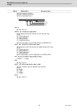
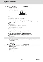
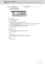
When setting the motor side encoder resolution in pulse (p) unit, set the number of pulses to four bite data
of SP098 (high-order) and SP020 (low-order) in pulse (p) unit.
When SP098=0, the setting unit of SP020 is (kp).
Refer to SP020 for details.
Related parameters: SP019, SP020, SP097
---Setting range---
-1 to 32767
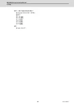
Not used. Set to "0".
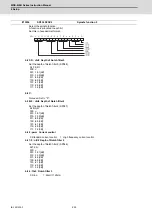
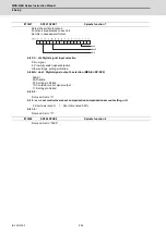
Set the scale model gain (position response) in OMR-FF control.
Set the same value as SV002(PGN).
Increase the setting value to perform a high-speed machining such as a fine arc or to improve the path error.
Lower the value when vibration occurs during acceleration/deceleration.
Set to "0" when not using OMR-FF control.
---Setting range---
0 to 300 (rad/s)
Not used. Set to "0".
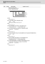
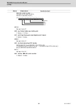
Set the current feed forward rate in OMR-FF control.
The standard setting is "10000".
Setting value of 0 is equal to "10000(100%)" setting.
Set to "0" when not using OMR-FF control.
---Setting range---
0 to 32767 (0.01%)
Set the current command value for when the open loop control is enabled.
When "0" is set, the state will be the same as when "50" is set.
When not using, set to "0".
The open loop control is enabled when "SP018/bit1" is set to "1".
---Setting range---
0 to 999 (Short-time rated %)
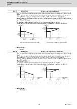
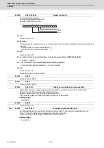
Set the time required to cut off the gate when turning OFF/ON the coil switch contactor.
The value should be longer than the coil switch contactor's OFF/ON time.
The standard setting is "150".
---Setting range---
0 to 3500 (ms)
Set the time required to limit the current immediately after the coil switch contactor ON/OFF is completed and
the gate is turned ON.
The standard setting is "250".
---Setting range---
0 to 3500 (ms)
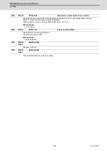
#13098
SP098 RNG2ex
Extension main side encoder resolution
#13099-
13105
SP099-SP105
#13106
SP106 PGM
OMR-FF scale model gain
#13107-
13111
SP107-SP111
#13112
SP112 IFF
OMR-FF current feed forward gain
#13113
SP113 OPLP
Current command value for open loop
#13114
SP114 MKT
Coil changeover gate cutoff timer
#13115
SP115 MKT2
Coil changeover current limit timer
Summary of Contents for MDS-E
Page 1: ......
Page 3: ......
Page 15: ......
Page 17: ......
Page 19: ......
Page 21: ......
Page 31: ......
Page 32: ...1 IB 1501229 F 1 Installation ...
Page 76: ...45 IB 1501229 F 2 Wiring and Connection ...
Page 132: ...101 IB 1501229 F 3 Safety Function ...
Page 142: ...111 IB 1501229 F 4 Setup ...
Page 277: ...MDS E EH Series Instruction Manual 4 Setup 246 IB 1501229 F ...
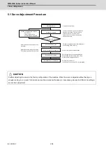
Page 278: ...247 IB 1501229 F 5 Servo Adjustment ...
Page 351: ...MDS E EH Series Instruction Manual 5 Servo Adjustment 320 IB 1501229 F ...
Page 352: ...321 IB 1501229 F 6 Spindle Adjustment ...
Page 404: ...373 IB 1501229 F 7 Troubleshooting ...
Page 455: ...MDS E EH Series Instruction Manual 7 Troubleshooting 424 IB 1501229 F ...
Page 456: ...425 IB 1501229 F 8 Maintenance ...
Page 475: ...MDS E EH Series Instruction Manual 8 Maintenance 444 IB 1501229 F ...
Page 476: ...445 IB 1501229 F 9 Power Backup System ...
Page 494: ...463 IB 1501229 F 10 Appx 1 Cable and Connector Assembly ...
Page 504: ...473 IB 1501229 F 11 Appx 2 D A Output Specifications for Drive Unit ...
Page 514: ...483 IB 1501229 F 12 Appx 3 Protection Function ...
Page 523: ...MDS E EH Series Instruction Manual 12 Appx 3 Protection Function 492 IB 1501229 F ...
Page 524: ...493 IB 1501229 F 13 Appx 4 Compliance to EC Directives ...
Page 528: ...497 IB 1501229 F 14 Appx 5 EMC Installation Guidelines ...
Page 540: ...509 IB 1501229 F 15 Appx 6 Higher Harmonic Suppression Measure Guidelines ...
Page 550: ......
Page 554: ......


