MDS-E/EH Series Instruction Manual
1 Installation
34
IB-1501229-F
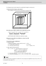
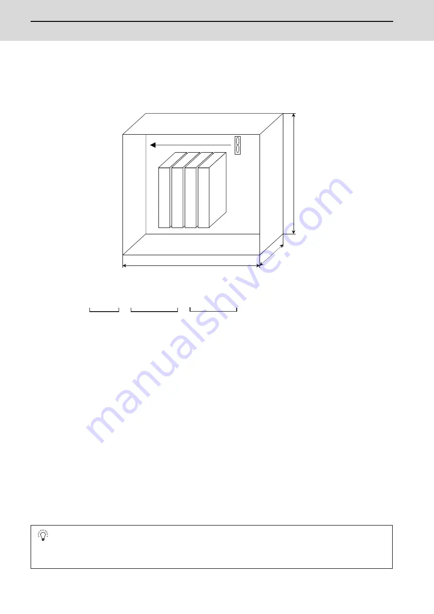
The following shows a calculation example for considering heat radiation countermeasures.
< Control panel outline dimension (assumption) >
When installing four units which have the heating value in the panel of 15W
Heat radiation area (A): When a bottom section contacts with a machine
(Note) Actually, sections contacting other objects are excluded.
Heating value in panel (W): when installing four units which are 15W
W = 15 × 4 = 60 (W)
< Considering necessity of agitating fan >
1 Temperature standard
(1) Standard of temperature in panel (around each unit) T
≦
55°C
(2) External peripheral temperature Ta = 0 to 45°C
(3) Internal temperature rise value DT = T - Ta (MAX) = 10°C
2 Cooling capacity of control panel (W1)
W1 = U × A × DT DT = Internal temperature rise value (=10°C)
U = 6W/m
2
• °C (with internal agitating fan)
4W/m
2
• °C (without internal agitating fan)
A = Effective heat radiation area (m
2
)
(1) With internal agitating fan W1 = 6 × 1.26 × 10 = 75.6 (W) > 60 (W)
(2) Without internal agitating fan W1 = 4 × 1.26 × 10 = 50.4 (W) < 60 (W) -- Internal fan is required.
POINT
Measure an actual internal temperature, and install a fan or heat exchanger which agitates the heat at the top of the unit if
the temperature rise exceeds 10°C.
Top of panel inside Fan for agitating
600
300
600
A = 0.6 × 0.3 + 0.6 × 0.6 × 2 + 0.6 × 0.3 × 2 = 1.26 (m )
2
(Top face) (Front/back face)
(Side face)
Summary of Contents for MDS-E
Page 1: ......
Page 3: ......
Page 15: ......
Page 17: ......
Page 19: ......
Page 21: ......
Page 31: ......
Page 32: ...1 IB 1501229 F 1 Installation ...
Page 76: ...45 IB 1501229 F 2 Wiring and Connection ...
Page 132: ...101 IB 1501229 F 3 Safety Function ...
Page 142: ...111 IB 1501229 F 4 Setup ...
Page 277: ...MDS E EH Series Instruction Manual 4 Setup 246 IB 1501229 F ...
Page 278: ...247 IB 1501229 F 5 Servo Adjustment ...
Page 351: ...MDS E EH Series Instruction Manual 5 Servo Adjustment 320 IB 1501229 F ...
Page 352: ...321 IB 1501229 F 6 Spindle Adjustment ...
Page 404: ...373 IB 1501229 F 7 Troubleshooting ...
Page 455: ...MDS E EH Series Instruction Manual 7 Troubleshooting 424 IB 1501229 F ...
Page 456: ...425 IB 1501229 F 8 Maintenance ...
Page 475: ...MDS E EH Series Instruction Manual 8 Maintenance 444 IB 1501229 F ...
Page 476: ...445 IB 1501229 F 9 Power Backup System ...
Page 494: ...463 IB 1501229 F 10 Appx 1 Cable and Connector Assembly ...
Page 504: ...473 IB 1501229 F 11 Appx 2 D A Output Specifications for Drive Unit ...
Page 514: ...483 IB 1501229 F 12 Appx 3 Protection Function ...
Page 523: ...MDS E EH Series Instruction Manual 12 Appx 3 Protection Function 492 IB 1501229 F ...
Page 524: ...493 IB 1501229 F 13 Appx 4 Compliance to EC Directives ...
Page 528: ...497 IB 1501229 F 14 Appx 5 EMC Installation Guidelines ...
Page 540: ...509 IB 1501229 F 15 Appx 6 Higher Harmonic Suppression Measure Guidelines ...
Page 550: ......
Page 554: ......

