MDS-E/EH Series Instruction Manual
4 Setup
146
IB-1501229-F
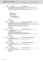
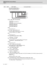
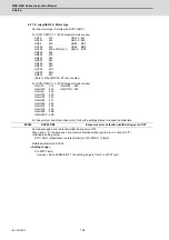
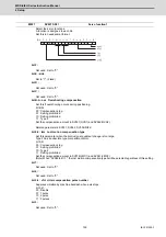
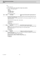
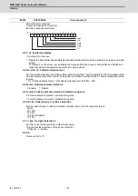
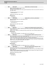
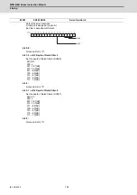
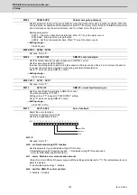
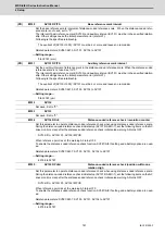
MDS-EJ/EJH Series: Regenerative resistor type
Set the regenerative resistor type.
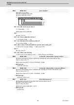
bit F-8 : amp(bit F-C) / rtyp(bit B-8)
Resistor built-in drive unit : 10
Setting prohibited : 11
MR-RB032 : 12
MR-RB12 or GZG200W39OHMK : 13
MR-RB32 or GZG200W120OHMK 3 units connected in parallel : 14
MR-RB30 or GZG200W39OHMK 3 units connected in parallel : 15
MR-RB50 or GZG300W39OHMK 3 units connected in parallel : 16
MR-RB31 or GZG200W20OHMK 3 units connected in parallel : 17
MR-RB51 or GZG300W20OHMK 3 units connected in parallel : 18
Setting prohibited : 19-1F
Setting prohibited : 20-23
FCUA-RB22 : 24
FCUA-RB37 : 25
FCUA-RB55 : 26
FCUA-RB75/2 : 27
Setting prohibited : 28
R-UNIT2 : 29
Setting prohibited : 2A-2C
FCUA-RB75/2 2 units connected in parallel : 2D
FCUA-RB55 2 units connected in parallel : 2E
Setting prohibited : 2F
MR-RB1H-4 : 33
MR-RB3M-4 : 34
MR-RB3G-4 : 35
MR-RB5G-4 : 36
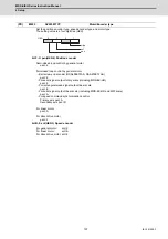
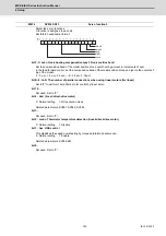
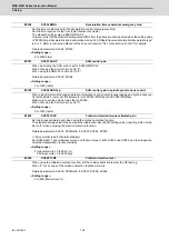
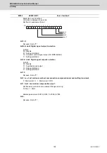
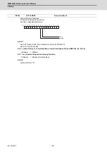
bit 7-4 : emgx External emergency stop function
Set the external emergency stop function.
0: Disable 4: Enable
bit 3-0 :
Not used. Set to "0".
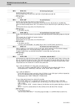
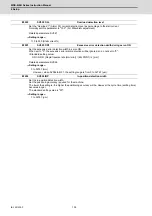
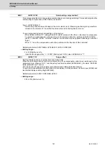
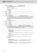
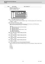
Set the motor axis conversion total load inertia including motor itself in proportion to the motor inertia.
SV037(JL)=(Jm+Jl)/Jm×100
Jm: Motor inertia
Jl: Motor axis conversion load inertia
For linear motor, set the gross mass of the moving sections in kg unit.
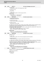
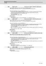
<<Drive monitor load inertia ratio display>>
Set SV035/bitF=1 and imbalance torque and friction torque to both SV032 and SV045, and then repeat ac-
celeration/deceleration for several times.
---Setting range---
For general motor: 0 to 5000 (%)
For linear motor 0 to 5000 (kg)
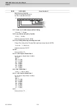
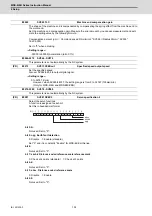
#2237
SV037 JL
Load inertia scale
emgx
rtyp
amp
0
0
0 0
Summary of Contents for MDS-E
Page 1: ......
Page 3: ......
Page 15: ......
Page 17: ......
Page 19: ......
Page 21: ......
Page 31: ......
Page 32: ...1 IB 1501229 F 1 Installation ...
Page 76: ...45 IB 1501229 F 2 Wiring and Connection ...
Page 132: ...101 IB 1501229 F 3 Safety Function ...
Page 142: ...111 IB 1501229 F 4 Setup ...
Page 277: ...MDS E EH Series Instruction Manual 4 Setup 246 IB 1501229 F ...
Page 278: ...247 IB 1501229 F 5 Servo Adjustment ...
Page 351: ...MDS E EH Series Instruction Manual 5 Servo Adjustment 320 IB 1501229 F ...
Page 352: ...321 IB 1501229 F 6 Spindle Adjustment ...
Page 404: ...373 IB 1501229 F 7 Troubleshooting ...
Page 455: ...MDS E EH Series Instruction Manual 7 Troubleshooting 424 IB 1501229 F ...
Page 456: ...425 IB 1501229 F 8 Maintenance ...
Page 475: ...MDS E EH Series Instruction Manual 8 Maintenance 444 IB 1501229 F ...
Page 476: ...445 IB 1501229 F 9 Power Backup System ...
Page 494: ...463 IB 1501229 F 10 Appx 1 Cable and Connector Assembly ...
Page 504: ...473 IB 1501229 F 11 Appx 2 D A Output Specifications for Drive Unit ...
Page 514: ...483 IB 1501229 F 12 Appx 3 Protection Function ...
Page 523: ...MDS E EH Series Instruction Manual 12 Appx 3 Protection Function 492 IB 1501229 F ...
Page 524: ...493 IB 1501229 F 13 Appx 4 Compliance to EC Directives ...
Page 528: ...497 IB 1501229 F 14 Appx 5 EMC Installation Guidelines ...
Page 540: ...509 IB 1501229 F 15 Appx 6 Higher Harmonic Suppression Measure Guidelines ...
Page 550: ......
Page 554: ......

