

MDS-E/EH Series Instruction Manual
1 Installation
13
IB-1501229-F
1.2.2 Balancing the Spindle Motor (Unit)
When a spindle motor is driven at a high speed with unbalance generated on the rotor, the whirling load is generated and
the load to the motor's internal bearings is increased. Thus abnormal vibration, and/or damages known as fretting or
flaking occurs to the bearings, which may result in shorter bearing life. Therefore, it is important to balance the rotation so
that great vibration does not occur during rotation at high speed.
When balancing the spindle motor, perform to the entire rotational objects including the gear, pulley, coupling, etc. that
are attached directly on the motor shaft. Provide a balancing mechanism including screw holes on the fittings while
measuring the vibration so that the vibration is suppressed to the specified level or lower during high speed rotation.
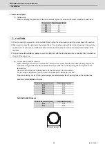
(1) Fittings for the motor shaft
When you select fittings for the motor shaft, such as a gear, pulley, and coupling, choose those that meet the motor
specifications (shaft diameter, rotation speed and output torque).
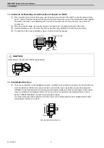
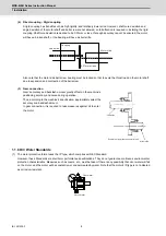
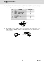
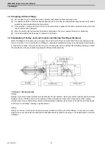
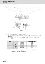
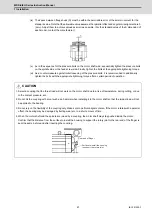
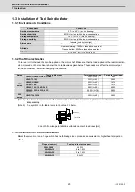
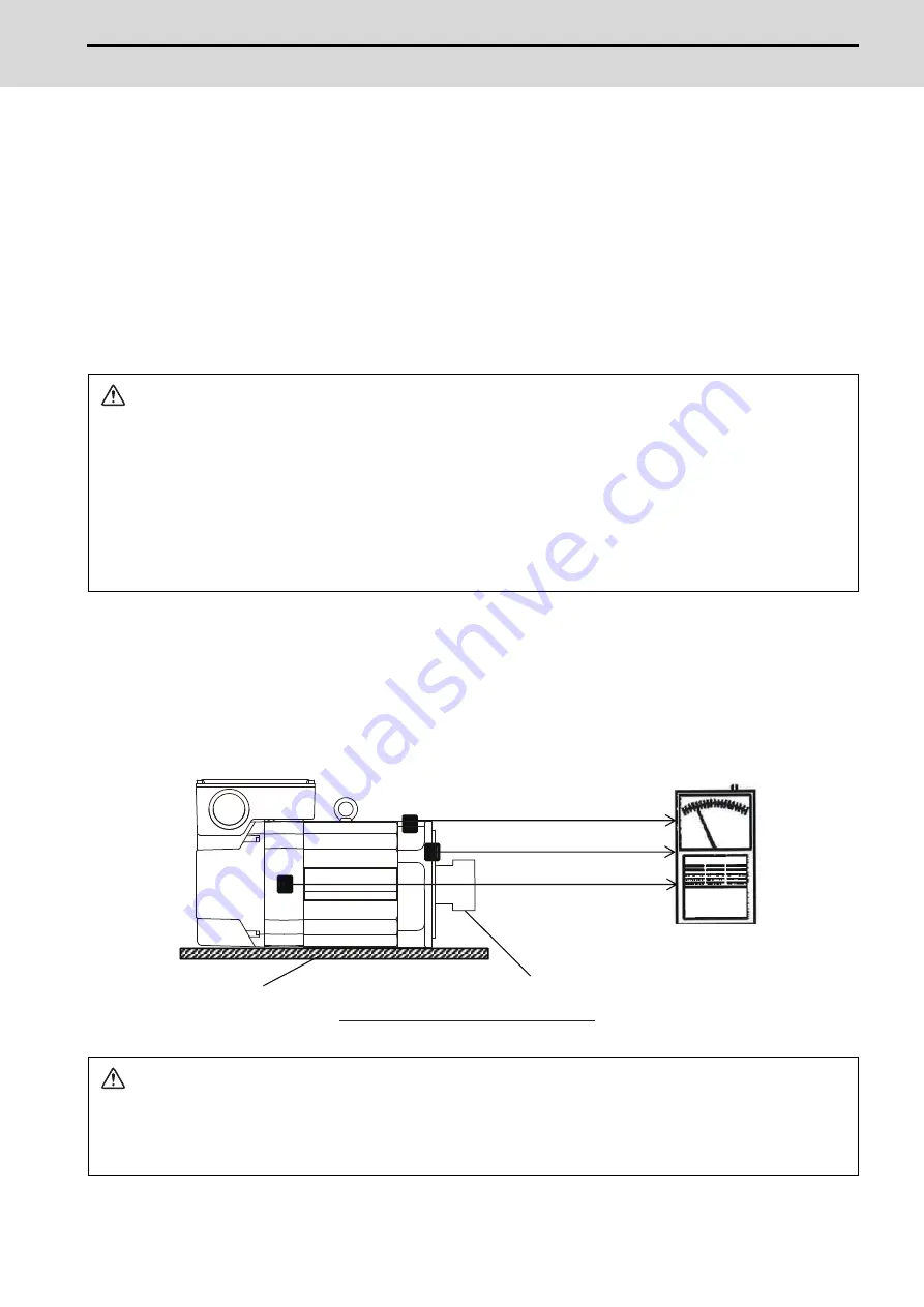
(2) How to measure the unbalance
After attaching the fittings such as gear, pulley, and coupling, carry out no-load operation, and use an
accelerometer or vibrometer compatible with frequency analysis to confirm the vibration on the points as illustrated
below (on the brackets where the bearings are stored).
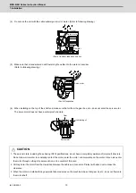
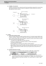
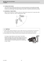
Make sure to place the motor on a cushioning mat to avoid vibration to the spindle from external sources during
measurement. Reaction torque is generated when accelerating/decelerating the motor, so securely fix the motor
with a belt, etc. to avoid rolling during measurement.
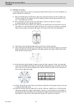
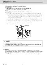
CAUTION
1. We consider key-less shaft as standard in order to simplify balancing procedure of such as gear, pulley, and coupling.
We recommend you to choose a gear, pulley and coupling that have a fully symmetric shape, and arrange screw holes
on their end faces at short and equal intervals in the circumferential direction.
2. Use a fastener such as a shaft lock element to fix those fittings to the motor shaft.
3. When you attach fittings to the motor shaft, be careful not to apply excessive impact by striking with a hammer, etc. This
may cause the shaft distortion and bearing damage.
4. When using screws for balancing, apply thread locker on the screws after balancing.
CAUTION
1. Make sure to place the motor on a cushioning mat to avoid resonance with surrounding devices during measurement.
2. Always secure the spindle motor body with a belt, etc. because it may roll due to the reaction torque generated during
acceleration/deceleration operation.
Load side bracket (axial direction)
Counter load side bracket (horizontal)
Load
side bracket (horizontal, vertical)
Locations where motor vibration is measured
Measuring device
Coupling
Cushioning mat
Summary of Contents for MDS-E
Page 1: ......
Page 3: ......
Page 15: ......
Page 17: ......
Page 19: ......
Page 21: ......
Page 31: ......
Page 32: ...1 IB 1501229 F 1 Installation ...
Page 76: ...45 IB 1501229 F 2 Wiring and Connection ...
Page 132: ...101 IB 1501229 F 3 Safety Function ...
Page 142: ...111 IB 1501229 F 4 Setup ...
Page 277: ...MDS E EH Series Instruction Manual 4 Setup 246 IB 1501229 F ...
Page 278: ...247 IB 1501229 F 5 Servo Adjustment ...
Page 351: ...MDS E EH Series Instruction Manual 5 Servo Adjustment 320 IB 1501229 F ...
Page 352: ...321 IB 1501229 F 6 Spindle Adjustment ...
Page 404: ...373 IB 1501229 F 7 Troubleshooting ...
Page 455: ...MDS E EH Series Instruction Manual 7 Troubleshooting 424 IB 1501229 F ...
Page 456: ...425 IB 1501229 F 8 Maintenance ...
Page 475: ...MDS E EH Series Instruction Manual 8 Maintenance 444 IB 1501229 F ...
Page 476: ...445 IB 1501229 F 9 Power Backup System ...
Page 494: ...463 IB 1501229 F 10 Appx 1 Cable and Connector Assembly ...
Page 504: ...473 IB 1501229 F 11 Appx 2 D A Output Specifications for Drive Unit ...
Page 514: ...483 IB 1501229 F 12 Appx 3 Protection Function ...
Page 523: ...MDS E EH Series Instruction Manual 12 Appx 3 Protection Function 492 IB 1501229 F ...
Page 524: ...493 IB 1501229 F 13 Appx 4 Compliance to EC Directives ...
Page 528: ...497 IB 1501229 F 14 Appx 5 EMC Installation Guidelines ...
Page 540: ...509 IB 1501229 F 15 Appx 6 Higher Harmonic Suppression Measure Guidelines ...
Page 550: ......
Page 554: ......


