MDS-E/EH Series Instruction Manual
1 Installation
20
IB-1501229-F
(c) Installation of coupling
The following describes how to install a coupling using a product by Miki Pulley. Contact the manufacturer for
details of cautions and confirmation.
(i)
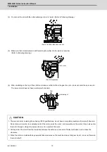
Make sure that the pressure bolts of the coupling are loosened, and remove rust, dirt, and grease, etc.
from the shaft and the inner diameter part of the coupling. (Grease should be wiped away with a cloth,
etc., or by degreasing as required.)
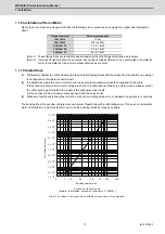
(ii) When inserting the coupling into the motor shaft, make sure that no excessive force such as
compression, tension, etc. is applied to the element.
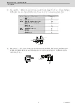
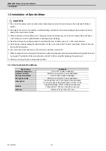
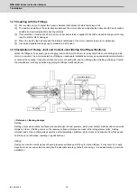
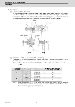
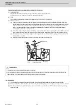
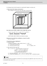
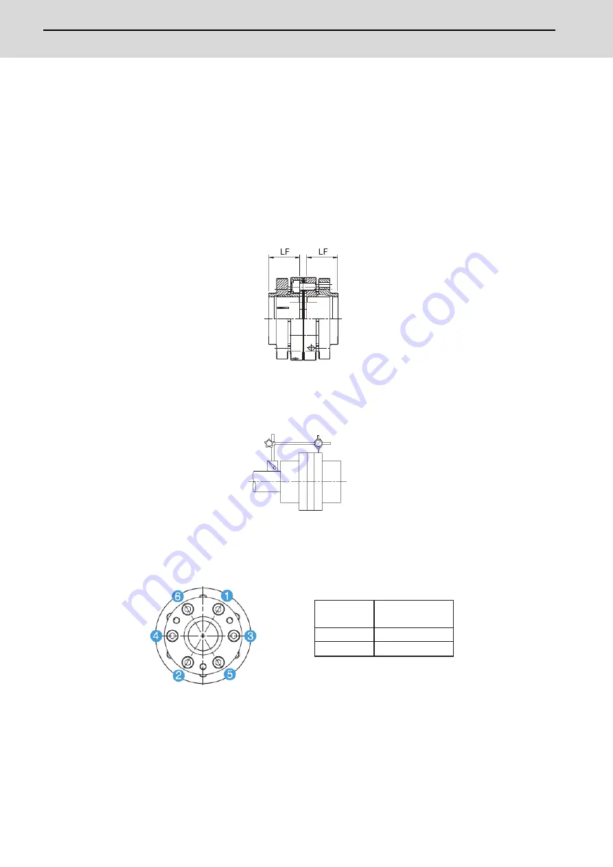
(iii) Make sure that the insertion length of the coupling into the motor shaft is kept in the position where the
target shaft is in contact with the entire length of the flange of the coupling (LF dimension) as illustrated
below. (For the variation of models and the length of LF of each model, contact the manufacturer.)
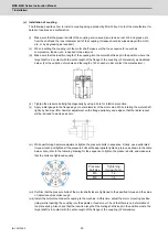
(iv) Tighten the pressure bolts lightly diagonally by using a bore for rotation prevention.
(v) Apply a dial gauge to the flange edge or outer diameter of the motor side. While rotating the motor shaft
lightly by hand, perform hammer adjustment on the flange periphery and edge so that the radial runout
will be reduced to as close as zero.
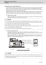
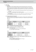
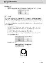
(vi) While performing hammer adjustment, tighten the pressure bolts in sequence. Finally, use a calibrated
torque wrench and tighten all the pressure bolts at the appropriate tightening torque as shown in the table
below. Also, refer to the following drawing for the sequence to tighten the pressure bolts, and make sure
that the bolts are tightened equally.
(vii) Confirm that the pressure bolts of the motor shaft side are tightened to the specified torque and the value
of radial runout is small enough.
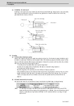
(viii) Install the motor mounted with coupling to the machine. At this time, adjust the motor mounting position
(inlay) while inserting the coupling into the spindle or feed screw. Check that there is no deformation of
the plate spring. Also check that the insertion length of the mating shaft is kept in the position where the
target shaft is in contact with the entire length of the flange of the coupling (LF dimension).
M6
M8
14
34
Pressure
bolt size
Tightening
torque (N•m)
Summary of Contents for MDS-E
Page 1: ......
Page 3: ......
Page 15: ......
Page 17: ......
Page 19: ......
Page 21: ......
Page 31: ......
Page 32: ...1 IB 1501229 F 1 Installation ...
Page 76: ...45 IB 1501229 F 2 Wiring and Connection ...
Page 132: ...101 IB 1501229 F 3 Safety Function ...
Page 142: ...111 IB 1501229 F 4 Setup ...
Page 277: ...MDS E EH Series Instruction Manual 4 Setup 246 IB 1501229 F ...
Page 278: ...247 IB 1501229 F 5 Servo Adjustment ...
Page 351: ...MDS E EH Series Instruction Manual 5 Servo Adjustment 320 IB 1501229 F ...
Page 352: ...321 IB 1501229 F 6 Spindle Adjustment ...
Page 404: ...373 IB 1501229 F 7 Troubleshooting ...
Page 455: ...MDS E EH Series Instruction Manual 7 Troubleshooting 424 IB 1501229 F ...
Page 456: ...425 IB 1501229 F 8 Maintenance ...
Page 475: ...MDS E EH Series Instruction Manual 8 Maintenance 444 IB 1501229 F ...
Page 476: ...445 IB 1501229 F 9 Power Backup System ...
Page 494: ...463 IB 1501229 F 10 Appx 1 Cable and Connector Assembly ...
Page 504: ...473 IB 1501229 F 11 Appx 2 D A Output Specifications for Drive Unit ...
Page 514: ...483 IB 1501229 F 12 Appx 3 Protection Function ...
Page 523: ...MDS E EH Series Instruction Manual 12 Appx 3 Protection Function 492 IB 1501229 F ...
Page 524: ...493 IB 1501229 F 13 Appx 4 Compliance to EC Directives ...
Page 528: ...497 IB 1501229 F 14 Appx 5 EMC Installation Guidelines ...
Page 540: ...509 IB 1501229 F 15 Appx 6 Higher Harmonic Suppression Measure Guidelines ...
Page 550: ......
Page 554: ......

