MDS-E/EH Series Instruction Manual
4 Setup
123
IB-1501229-F
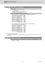
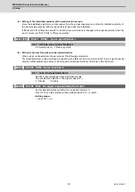
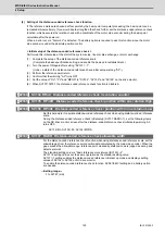
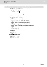
(2) Setting of the distance-coded reference check function
If The reference marks are checked at four points by the basic point computer processing, the basic point can be
recreated almost certainly. If you would like to strengthen the check further, set the distance-coded reference check
function, which executes the relation check with a coordinate of the motor side encoder during the basic point
calculation after the power-on.
When an error occurs, "Alarm 42" is detected. The battery option is required to use this function since the motor
side encoder is under the absolute position control.
< Initial setup of the distance-coded reference check >
Performed this initial setup at the start of the system setup, linear scale exchange, or motor exchange.
(1) Complete the setup of the distance-coded reference scale.
( Complete the base specification setting, and enable the basic point establishment.)
(2) Turn the power ON again after setting "SV137 = -1".
( Under a state of the distance-coded reference check initial setup warning "A3".)
(3) Perform the reference point return.
(4) Conform that the warning "A3" turns OFF.
(5) Set the value of "Rn", "Pn" and "MPOS" to "SV134", "SV135" and "SV136" on the drive monitor.
(6) When SV137=32767, the distance-coded reference check function is disabled.
【
#2334
】
SV134 RRn0 Distance-coded reference check / revolution counter
【
#2335
】
SV135 RPn0H Distance-coded reference check /position within one rotation High
【
#2336
】
SV136 RPn0L Distance-coded reference check / position within one rotation Low
Set this parameter to operate distance-coded reference check when using distance-coded reference
scale.
During the distance-coded reference check initial setup (SV137:RAER=-1), set the following items
on the NC drive monitor screen after the distance-coded reference check initial setup warning A3
turns OFF.
SV134=Rn, SV135=Pn, SV136=MPOS
【
#2337
】
SV137 RAER Distance-coded reference check allowable width
For the distance-coded reference check function when using distance-coded reference scale, set the
allowable gap from the reference point position data calculated by the main side encoder. When the
gap exceeds the allowable range, reference point created by distance-code is judged as wrong and
detects alarm 42.
The standard setting value is "basic reference mark interval (SV130) / 4".
SV137=0 setting carries out the same operation as the standard setting value.
SV137=-1 setting enables the distance-coded reference initial set up mode and displays setting
values of SV134 to SV136 on NC drive monitor.
To enable the distance-coded reference check function, SV081/bit3=1setting and a battery option
are needed.
---Setting range---
-1 to 32767 (mm)
Summary of Contents for MDS-E
Page 1: ......
Page 3: ......
Page 15: ......
Page 17: ......
Page 19: ......
Page 21: ......
Page 31: ......
Page 32: ...1 IB 1501229 F 1 Installation ...
Page 76: ...45 IB 1501229 F 2 Wiring and Connection ...
Page 132: ...101 IB 1501229 F 3 Safety Function ...
Page 142: ...111 IB 1501229 F 4 Setup ...
Page 277: ...MDS E EH Series Instruction Manual 4 Setup 246 IB 1501229 F ...
Page 278: ...247 IB 1501229 F 5 Servo Adjustment ...
Page 351: ...MDS E EH Series Instruction Manual 5 Servo Adjustment 320 IB 1501229 F ...
Page 352: ...321 IB 1501229 F 6 Spindle Adjustment ...
Page 404: ...373 IB 1501229 F 7 Troubleshooting ...
Page 455: ...MDS E EH Series Instruction Manual 7 Troubleshooting 424 IB 1501229 F ...
Page 456: ...425 IB 1501229 F 8 Maintenance ...
Page 475: ...MDS E EH Series Instruction Manual 8 Maintenance 444 IB 1501229 F ...
Page 476: ...445 IB 1501229 F 9 Power Backup System ...
Page 494: ...463 IB 1501229 F 10 Appx 1 Cable and Connector Assembly ...
Page 504: ...473 IB 1501229 F 11 Appx 2 D A Output Specifications for Drive Unit ...
Page 514: ...483 IB 1501229 F 12 Appx 3 Protection Function ...
Page 523: ...MDS E EH Series Instruction Manual 12 Appx 3 Protection Function 492 IB 1501229 F ...
Page 524: ...493 IB 1501229 F 13 Appx 4 Compliance to EC Directives ...
Page 528: ...497 IB 1501229 F 14 Appx 5 EMC Installation Guidelines ...
Page 540: ...509 IB 1501229 F 15 Appx 6 Higher Harmonic Suppression Measure Guidelines ...
Page 550: ......
Page 554: ......

