[
VII
Control ]
- 88 -
HWE10060
GB
Control Method
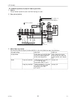
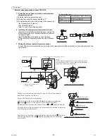
-12- Automatic operation of pump for freeze-up protection
1. Purpose
This is a function to protect the water circuit from freezing up in winter.
2. Pump
wire
connection
3. Natural
freeze-up
protection
The units will operate according to the dip switch SW2-1 on the control board as shown in the table below.
Dip switch settings
SW2-1 OFF
SW2-1 ON
Control method
Natural freeze-up protection based
on both the outside temperature
and the water temperature
Natural freeze-up protection
based on both the outside tem-
perature and the water tempera-
ture
Details
Pump start conditions
"Outside temperature is within ±1 ºC
of 1 ºC" OR "Inlet water
temperatureis within ±1 of 3 ºC "
Same as left
Pump stop conditions
"Outside temperature is more than
±1ºC of 3 ºC" OR "Inlet water
temperature is more than
±1ºC of 5 ºC"
Same as left
7 6 5
3 2 1
4
1
2
4
1
2
3
5
6
7
1
2
3
4
2
3
4
5
7 6
1
31
2
power supply
3N~
50Hz
380/400/415V
yellow
CN512
H21
H20
N
X21
X20
X21
X20
Drain pan heater
Emargency
signal
(for extra
heater)
X09
X08
Error display output
Operation display output
72C
Pump operation command output
X04
X05
X06
X07
70
A
B
CN102
MA
MB
No-voltage contact output
SV2
73
72 71
75
74
CN510
blue
CN511
TO SUB BOX TB3
pump error
51P
52P
ELB2
M
3~
MP
L2
LED2:CPU in operation
Transmission cable for multiple unit control
Measurement terminal for maintenance(M-NET)
PL
L1
52P
L3
F2
Contorol
power circuit
TB6
TB5
CNDC
Pink
CN52C
red
Summary of Contents for CAHV-P500YA-HPB
Page 1: ...Service Handbook Service Handbook CAHV P500YA HPB Model 2011 HOT WATER HEAT PUMP ...
Page 7: ...CONTENTS HWE10060 GB ...
Page 9: ... 2 HWE10060 GB ...
Page 19: ... 12 HWE10060 GB ...
Page 37: ... 30 HWE10060 GB ...
Page 46: ... 39 HWE10060 GB IV Remote Controller 1 Using the Remote Controller 41 2 Function Settings 46 ...
Page 47: ... 40 HWE10060 GB ...
Page 55: ... IV Remote Controller 48 HWE10060 GB ...
Page 56: ... 49 HWE10060 GB V Electrical Wiring Diagram 1 Electrical Wiring Diagram 51 ...
Page 57: ... 50 HWE10060 GB ...
Page 61: ... V Electrical Wiring Diagram 54 HWE10060 GB ...
Page 63: ... 56 HWE10060 GB ...
Page 67: ... VI Refrigerant Circuit 60 HWE10060 GB ...
Page 69: ... 62 HWE10060 GB ...
Page 101: ... VII Control 94 HWE10060 GB ...
Page 103: ... 96 HWE10060 GB ...
Page 109: ... VIII Test Run Mode 102 HWE10060 GB ...
Page 111: ... 104 HWE10060 GB ...
Page 155: ... IX Troubleshooting 148 HWE10060 GB ...
Page 156: ... 149 HWE10060 GB X Attachments 1 R407C saturation temperature table 151 ...
Page 157: ... 150 HWE10060 GB ...
Page 159: ... X Attachments 152 HWE10060 GB ...

