[
II
Restrictions ]
- 20 -
HWE10060
GB
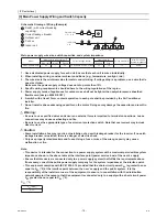
(2) System configuration procedures: Individual system
1. Set the dip switches on the MAIN circuit board.
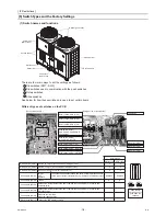
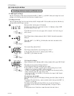
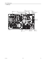
Switch settings on the MAIN circuit
Set the dip switches (labeled A in the figure at
right) that correspond to the items below,
according to the local system.
• Water temperature control based on the
external water temperature reading
• Water temperature control based on the inlet
water temperature
Refer to "Dip switch settings table" (page 63) for
further details.
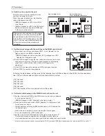
2. Switch on the power to the unit.
Check for loose or incorrect wiring, and then
switch on the power to the unit.
When the power is switched on, the following
codes will appear on the LED:
• [EEEE] will appear on LED1 in the MAIN
circuit board (labeled A in the figure at right).
• [9999] will appear on LED1 in the SUB circuit
board (labeled B in the figure at right).
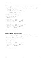
3. Set the preset values with the switches on the MAIN circuit board.
(1) Press either one of the push switches SWP1, 2, or 3 (labeled A in the
figure at right) on the MAIN circuit board.
*[EEEE] will disappear, and an item code ([101]) will appear on LED1
(labeled B in the figure at right).
(2) Use SWP3 to toggle through the item codes and select an item code to
change its current value. (The item codes will appear in the following
order: [101]→[102]→[104]→[105]→ [107]→[101] (back to the
beginning).)
(3) Use SWP1 to increase the value and SWP2 to decrease the value.
(4) Press SWP3 to save the changed value.
Following the steps above, set the value for the following items as necessary.
[101] Not used
[102] Not used
[104] Not used
[105] Not used
[107] Total number of units in the system (Default = 1) (Leave it as it is.)
If the system is not started up for five minutes after the power is turned on (with the [EEEE] being displayed on the
MAIN circuit), an error code [6500] or [7133] will appear on the SUB circuit. This error code will automatically light
off once the system startup procedure is completed.
A
B
Unit (SUB circuit)
Unit (MAIN circuit)
10’s digit (0) 1’s digit (1)
(0)
10’s digit (5) 1’s digit (1)
(0)
A
B
Unit (SUB circuit)
Unit (MAIN circuit)
10’s digit (0) 1’s digit (1)
(0)
10’s digit (5) 1’s digit (1)
(0)
B
A
Unit (MAIN circuit)
10’s digit (0) 1’s digit (1)
(0)
4
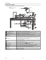
. Perform an initial setup. (MAIN circuit side)
(1) Set the rotary switch SWU3 (labeled A in the figure at right) to "F."
[EEEE] will appear in LED1 (labeled B in the figure at right). *1
(2) Press and hold the push switch (SWP3) (labeled C in the figure at right)
for one second or longer.
• While the system is starting up [9999] will appear on LED1 (labeled B
in the figure at right).
• When start-up is complete, a control property [0012] will appear.
• Then five seconds later [FFFF] will appear.
(3) Set the rotary switch SWU3 (labeled A in the figure at right) back to "0."
The start-up process is complete, and the settings for such items as
clock, peak-demand control, schedule, and thermistor settings can now
be made.
*1 If the start-up process has already been completed, [FFFF] (instead of [EEEE]) will appear when the rotary switch SWU3 is set to "F."
A
B
C
Unit (MAIN circuit)
10’s digit (0) 1’s digit (1)
(0)
Summary of Contents for CAHV-P500YA-HPB
Page 1: ...Service Handbook Service Handbook CAHV P500YA HPB Model 2011 HOT WATER HEAT PUMP ...
Page 7: ...CONTENTS HWE10060 GB ...
Page 9: ... 2 HWE10060 GB ...
Page 19: ... 12 HWE10060 GB ...
Page 37: ... 30 HWE10060 GB ...
Page 46: ... 39 HWE10060 GB IV Remote Controller 1 Using the Remote Controller 41 2 Function Settings 46 ...
Page 47: ... 40 HWE10060 GB ...
Page 55: ... IV Remote Controller 48 HWE10060 GB ...
Page 56: ... 49 HWE10060 GB V Electrical Wiring Diagram 1 Electrical Wiring Diagram 51 ...
Page 57: ... 50 HWE10060 GB ...
Page 61: ... V Electrical Wiring Diagram 54 HWE10060 GB ...
Page 63: ... 56 HWE10060 GB ...
Page 67: ... VI Refrigerant Circuit 60 HWE10060 GB ...
Page 69: ... 62 HWE10060 GB ...
Page 101: ... VII Control 94 HWE10060 GB ...
Page 103: ... 96 HWE10060 GB ...
Page 109: ... VIII Test Run Mode 102 HWE10060 GB ...
Page 111: ... 104 HWE10060 GB ...
Page 155: ... IX Troubleshooting 148 HWE10060 GB ...
Page 156: ... 149 HWE10060 GB X Attachments 1 R407C saturation temperature table 151 ...
Page 157: ... 150 HWE10060 GB ...
Page 159: ... X Attachments 152 HWE10060 GB ...

