[
II
Restrictions ]
- 14 -
HWE10060
GB
[2] Types and Maximum allowable Length of Cables
1. Wiring
work
(1) Notes
1) Have all electrical work performed by an authorized electrician according to the local regulations and instructions in this man-
ual.
2) Install external transmission cables at least 5cm [1-31/32"] away from the power supply cable to avoid noise interference.
(Do not put the control cable and power supply cable in the same conduit tube.)
3) Provide grounding for the outdoor unit as required.
4) Run the cable from the electric box of the outdoor unit in such way that the box is accessible for servicing.
5) Do not connect power supply wiring to the terminal block for transmission line. Doing so will damage the electronic compo-
nents on the terminal block.
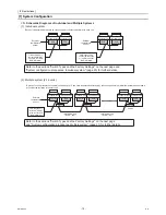
6) Use 2-core shielded cables as transmission cables.
Use a separate 2-core control cable for each refrigerant system. Do not use a single multiple-core cable to connect units that
belong to different refrigerant systems. The use of a multiple-core cable may result in signal transmission errors and malfunc-
tions.
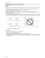
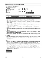
(2) Control wiring
Different types of control wiring are used for different systems.
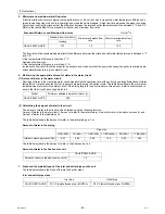
Types and maximum allowable length of cables
Control lines are categorized into 2 types: transmission line and remote controller line.
Use the appropriate type of cables and observe the maximum allowable length specified for a given system. If a given system
has a long transmission line or if a noise source is located near the unit, place the unit away from the noise source to reduce
noise interference.
2-core shielded cable
2-core shielded cable
2-core shielded cable
2-core shielded cable
MA MB
TB
3
MA MB
TB
3
TB
3
TB
3
TB3: Terminal block for transmission line
multiple-core cable
2-core shielded cable
2-core shielded cable
unit
unit
unit
MA MB
TB
3
MA MB
MA MB
MA MB
TB
3
unit
unit
unit
TB
3
unit
MA MB
TB
3
unit
MA MB
Summary of Contents for CAHV-P500YA-HPB
Page 1: ...Service Handbook Service Handbook CAHV P500YA HPB Model 2011 HOT WATER HEAT PUMP ...
Page 7: ...CONTENTS HWE10060 GB ...
Page 9: ... 2 HWE10060 GB ...
Page 19: ... 12 HWE10060 GB ...
Page 37: ... 30 HWE10060 GB ...
Page 46: ... 39 HWE10060 GB IV Remote Controller 1 Using the Remote Controller 41 2 Function Settings 46 ...
Page 47: ... 40 HWE10060 GB ...
Page 55: ... IV Remote Controller 48 HWE10060 GB ...
Page 56: ... 49 HWE10060 GB V Electrical Wiring Diagram 1 Electrical Wiring Diagram 51 ...
Page 57: ... 50 HWE10060 GB ...
Page 61: ... V Electrical Wiring Diagram 54 HWE10060 GB ...
Page 63: ... 56 HWE10060 GB ...
Page 67: ... VI Refrigerant Circuit 60 HWE10060 GB ...
Page 69: ... 62 HWE10060 GB ...
Page 101: ... VII Control 94 HWE10060 GB ...
Page 103: ... 96 HWE10060 GB ...
Page 109: ... VIII Test Run Mode 102 HWE10060 GB ...
Page 111: ... 104 HWE10060 GB ...
Page 155: ... IX Troubleshooting 148 HWE10060 GB ...
Page 156: ... 149 HWE10060 GB X Attachments 1 R407C saturation temperature table 151 ...
Page 157: ... 150 HWE10060 GB ...
Page 159: ... X Attachments 152 HWE10060 GB ...

