[
VIII
Test Run Mode ]
- 97 -
HWE10060
GB
VIII
Test Run Mode
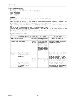
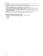
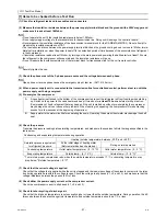
[1] Items to be checked before a Test Run
(1) Check for refrigerant leak and loose cables and connectors.
(2) Measure the insulation resistance between the power supply terminal block and the ground with a 500V megger and
make sure it reads at least 1.0Mohm.
Do not operate the unit if the insulation resistance is below 1.0Mohm.
Do not apply megger voltage to the terminal block for transmission line. Doing so will damage the controller board.
Never measure the insulation resistance of the transmission terminal block for the RA,RB,MA,MB(TB3). Do not attempt to
measure the insulation resistance of TB7.
The insulation resistance between the power supply terminal block and the ground could go down to close to 1Mohm imme-
diately after installation or when the power is kept off for an extended period of time because of the accumulation of refrigerant
in the compressor.
If insulation resistance reads at least 1Mohm, by turning on the main power and powering the belt heater for at least 12 hours,
the refrigerant in the compressor will evaporate and the insulation resistance will go up.
Do not measure the insulation resistance of the terminal block for transmission line for the unit remote controller.
Securely tighten the cap.
(3) Check the phase order of the 3-phase power source and the voltage between each phase.
Open phase or reverse phase causes the emergency stop of test run. (A471,4152 error)
(4) When a power supply unit is connected to the transmission line for centralized control, perform a test run with the
power supply unit being energized.
(5) Pre-energize the compressor.
(6) Check the pressure.
Translate the pressure readings into saturating temperatures, and make sure these values fall into the ranges specified in the
table below.
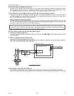
(7) Check that the correct voltage is applied.
Check that the voltage that is applied while the unit is stopped and the load-side voltage of the solenoid contactor in the relay
box during operation are within the voltage ranges. Check the voltage in all phases (L1, L2, and L3), and make sure that the
voltage imbalance between the phases is 2% or less.
(8) Check either the power supply current or the compressor current.
Check the compressor current in all phases (L1, L2, and L3).
(9) Check for short-cycling of discharge air.
Check that the intake air temperature is not unusually higher or lower than the outside temperature. During operation, the dif-
ference between the heat exchanger inlet temperature and outside temperature should be 1 ºC or less.
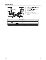
A.
A case heater is attached to the bottom of the compressor to prevent the refrigerant oil from foaming when starting
up. Switch on the power to the case heater and keep it turned on for
at least 12 hours
before starting a test run.
(Compression of liquid refrigerant that may happen if the unit is started up without pre-energizing the compressor
may damage the valve or cause other problems. When foaming is happening, the compressor will make cracking
sounds for a few seconds at the beginning of operation.)
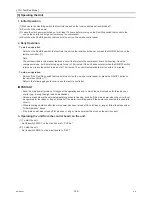
B.
Supply water to the water circuit before operating the pump. Operating the pump without water may damage the shaft
seal.
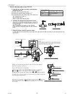
Condensing and evaporating temperatures during operation
Saturation pressure equivalent
to refrigerant pressure
Heating (outside temperature: between -20 ºC and +40 ºC)
At the initial stage of heating water
(Before water has been heated up)
During normal operation
Condensing temperature
Outlet water tempe (0 - 10 °C)
Outlet water tempe (0 - 5 °C)
Evaporating temperature
Outside temp. - (5 - 13 °C)
Outside temp. - (3 - 8 °C)*
* To maintain proper compression ratio, when the outside temperature exceeds 17 ºC, evaporating temperature may
drop below "(Outside temperature) - 8 ºC"
Summary of Contents for CAHV-P500YA-HPB
Page 1: ...Service Handbook Service Handbook CAHV P500YA HPB Model 2011 HOT WATER HEAT PUMP ...
Page 7: ...CONTENTS HWE10060 GB ...
Page 9: ... 2 HWE10060 GB ...
Page 19: ... 12 HWE10060 GB ...
Page 37: ... 30 HWE10060 GB ...
Page 46: ... 39 HWE10060 GB IV Remote Controller 1 Using the Remote Controller 41 2 Function Settings 46 ...
Page 47: ... 40 HWE10060 GB ...
Page 55: ... IV Remote Controller 48 HWE10060 GB ...
Page 56: ... 49 HWE10060 GB V Electrical Wiring Diagram 1 Electrical Wiring Diagram 51 ...
Page 57: ... 50 HWE10060 GB ...
Page 61: ... V Electrical Wiring Diagram 54 HWE10060 GB ...
Page 63: ... 56 HWE10060 GB ...
Page 67: ... VI Refrigerant Circuit 60 HWE10060 GB ...
Page 69: ... 62 HWE10060 GB ...
Page 101: ... VII Control 94 HWE10060 GB ...
Page 103: ... 96 HWE10060 GB ...
Page 109: ... VIII Test Run Mode 102 HWE10060 GB ...
Page 111: ... 104 HWE10060 GB ...
Page 155: ... IX Troubleshooting 148 HWE10060 GB ...
Page 156: ... 149 HWE10060 GB X Attachments 1 R407C saturation temperature table 151 ...
Page 157: ... 150 HWE10060 GB ...
Page 159: ... X Attachments 152 HWE10060 GB ...

