[
II
Restrictions ]
- 19 -
HWE10060
GB
[6] Configuring the Settings
1
2
3
4
<1> Making the settings
Use the LED display and the three push switches (SWP1 (↑), SWP2 (↓), and SWP3 (Enter)) to change the current
settings on the circuit board and to monitor various monitored values.
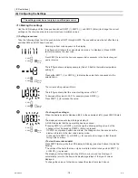
(1) Setting procedures
Take the following steps to set the push switches SWP1 through SWP3. These switches must be set after the dip
switches SW2 and SW3 have been set.
The settings must be set only by a qualified personnel.
Normally an item code appears on the display.
(The figure at left shows the case where item code 1 is displayed.) Press SWP3
(Enter) to advance the item code.
↓
Press SWP3 (Enter) until the item code appears that corresponds to the item to change or
monitor its value.
The left figure shows a display example (Code 13 Built-in thermistor temperature
setting 2).
↓
Press either SWP1 (↑) or SWP2 (↓) to display the value that corresponds to the
selected item.
The current setting value will blink.
↓
The left figure shows that the current setting value is "60.0."
To decrease this value to 58.0, for example, press SWP2 (↓).
Press SWP1 (↑) to increase the value.
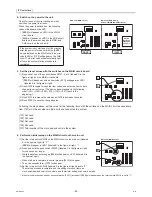
<To change the settings>
When the desired value is displayed (58.0 in the example at left), press SWP3 (Enter).
↓
The displayed value will stop blinking and stay lit.
A lit LED indicates that the new setting has been saved.
*Pressing SWP1 (↑) or SWP2 (↓) will change the blinking setting value, but the
change will not be saved until SWP3 (Enter) is pressed.
If SWP3 is not pressed within one minute, the change will not be saved and the
display will return to the item code display mode.
Press and hold SWP1 (↑) or SWP2 (↓) for one second or longer to fast forward
through the numbers.
<To view the monitored data>
Press SWP3 (Enter) while the LED display is blinking (see step 3 above) to stop the
blinking.
*The values of the items that can only be monitored will not change when SWP1 (↑)
or SWP2 (↓) is pressed.
The display will stop blinking and stay lit after a minute, and the display will
automatically return to the item code display regardless of the type of values
displayed.
To change the values of other items, repeat the steps from step 2 above.
SWP1
SWP3
Enter
SWP2
SWP1
SWP3
Enter
SWP2
SWP1
SWP3
Enter
SWP2
SWP1
SWP3
Enter
SWP2
Summary of Contents for CAHV-P500YA-HPB
Page 1: ...Service Handbook Service Handbook CAHV P500YA HPB Model 2011 HOT WATER HEAT PUMP ...
Page 7: ...CONTENTS HWE10060 GB ...
Page 9: ... 2 HWE10060 GB ...
Page 19: ... 12 HWE10060 GB ...
Page 37: ... 30 HWE10060 GB ...
Page 46: ... 39 HWE10060 GB IV Remote Controller 1 Using the Remote Controller 41 2 Function Settings 46 ...
Page 47: ... 40 HWE10060 GB ...
Page 55: ... IV Remote Controller 48 HWE10060 GB ...
Page 56: ... 49 HWE10060 GB V Electrical Wiring Diagram 1 Electrical Wiring Diagram 51 ...
Page 57: ... 50 HWE10060 GB ...
Page 61: ... V Electrical Wiring Diagram 54 HWE10060 GB ...
Page 63: ... 56 HWE10060 GB ...
Page 67: ... VI Refrigerant Circuit 60 HWE10060 GB ...
Page 69: ... 62 HWE10060 GB ...
Page 101: ... VII Control 94 HWE10060 GB ...
Page 103: ... 96 HWE10060 GB ...
Page 109: ... VIII Test Run Mode 102 HWE10060 GB ...
Page 111: ... 104 HWE10060 GB ...
Page 155: ... IX Troubleshooting 148 HWE10060 GB ...
Page 156: ... 149 HWE10060 GB X Attachments 1 R407C saturation temperature table 151 ...
Page 157: ... 150 HWE10060 GB ...
Page 159: ... X Attachments 152 HWE10060 GB ...

