[
IX
Troubleshooting ]
- 129 -
HWE10060
GB
Inverter
-5- Inverter
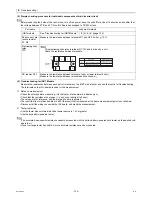
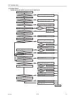
Replace only the compressor if only the compressor is found to be defective.
Replace only the fan motor if only the fan motor is found to be defective.
Replace the defective components if the inverter is found to be defective.
If both the compressor and the inverter are found to be defective, replace the defective component(s) of both devices.
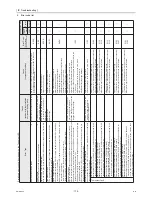
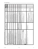
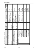
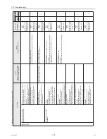
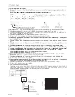
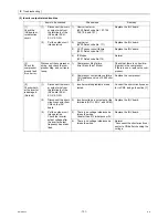
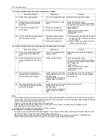
(1) Inverter-related problems: Troubleshooting and remedies
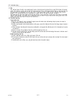
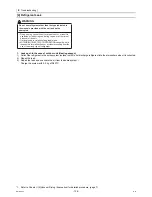
1) The INV board has a large-capacity electrolytic capacitor, in which residual voltage remains even after the main power is
turned off, posing a risk of electric shock. Before inspecting the inside of the control box, turn off the power, keep the unit off
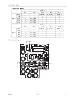
for at least 10 minutes, and confirm that the voltage between FT-P and FT-N on INV Board has dropped to DC20V or less.
(It takes about 10 minutes to discharge electricity after the power supply is turn off.)
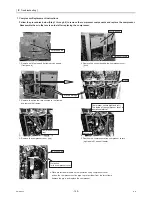
2) The IPM on the inverter becomes damaged if there are loose screws are connectors. If a problem occurs after replacing some
of the parts, mixed up wiring is often the cause of the problem. Check for proper connection of the wiring, screws, connectors,
and Faston terminals.
3) To avoid damage to the circuit board, do not connect or disconnect the inverter-related connectors with the main power turned
on.
4) Faston terminals have a locking function. Make sure the terminals are securely locked in place after insertion.
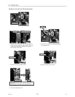
5) When the IPM or IGBT is replaced, apply a thin layer of heat radiation grease that is supplied evenly to these parts. Wipe off
any grease that may get on the wiring terminal to avoid terminal contact failure.
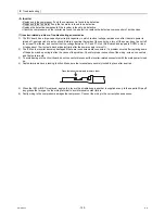
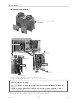
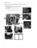
6) Faulty wiring to the compressor damages the compressor. Connect the wiring in the correct phase sequence.
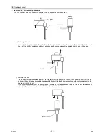
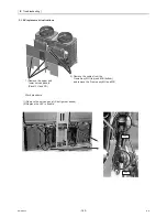
Press the tab on the terminals to remove them.
Summary of Contents for CAHV-P500YA-HPB
Page 1: ...Service Handbook Service Handbook CAHV P500YA HPB Model 2011 HOT WATER HEAT PUMP ...
Page 7: ...CONTENTS HWE10060 GB ...
Page 9: ... 2 HWE10060 GB ...
Page 19: ... 12 HWE10060 GB ...
Page 37: ... 30 HWE10060 GB ...
Page 46: ... 39 HWE10060 GB IV Remote Controller 1 Using the Remote Controller 41 2 Function Settings 46 ...
Page 47: ... 40 HWE10060 GB ...
Page 55: ... IV Remote Controller 48 HWE10060 GB ...
Page 56: ... 49 HWE10060 GB V Electrical Wiring Diagram 1 Electrical Wiring Diagram 51 ...
Page 57: ... 50 HWE10060 GB ...
Page 61: ... V Electrical Wiring Diagram 54 HWE10060 GB ...
Page 63: ... 56 HWE10060 GB ...
Page 67: ... VI Refrigerant Circuit 60 HWE10060 GB ...
Page 69: ... 62 HWE10060 GB ...
Page 101: ... VII Control 94 HWE10060 GB ...
Page 103: ... 96 HWE10060 GB ...
Page 109: ... VIII Test Run Mode 102 HWE10060 GB ...
Page 111: ... 104 HWE10060 GB ...
Page 155: ... IX Troubleshooting 148 HWE10060 GB ...
Page 156: ... 149 HWE10060 GB X Attachments 1 R407C saturation temperature table 151 ...
Page 157: ... 150 HWE10060 GB ...
Page 159: ... X Attachments 152 HWE10060 GB ...

