[
IX
Troubleshooting ]
- 116 -
HWE10060
GB
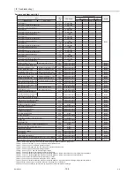
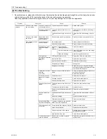
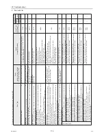
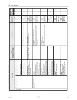
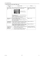
Open phase
When power is turned on
4115
A471
●The power supply frequency is at a
frequency other than 50 Hz.
●An open phase of three seconds or longer has been detected when the power
was turned on or when the power is on.
●Power supply frequency is determined based on the number of zero crossings (N)
per second (timed on a 5 msec timer and calculated in 20 msec increments).
●The error detection process will be terminated when one of the conditions 1 or 2 is
met wit thin one minute.
●If the error persists for longer than one minute, it will be regarded as a power supply
frequency fault.
1 95 times N 105 times [50 Hz]
2 115 times N 125 times [60 Hz]
3 N<95 times or N>125 times or 105 times<N<115 times
[Power supply frequency error]
●Noise filter fault (Voltage measured at CN3 connector is below 180 V.)
●Broken wiring between power supply terminal block TB2 and
TB1/TB4.
●Broken coil (L1, L2, or L3)
●Control board fault (If the items above are normal)
●Blown fuse F01, F02, or F03 on the noise filter board
●Blown fuse F06 on the control board
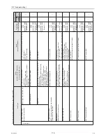
●Noise filter fault (Voltage measured at CN3 connector is below 180 V.)
●Broken wiring between power supply terminal block TB2 and
TB1/TB4.
●Broken coil (L1, L2, or L3)
(Preliminary error
code 4152 will
appear if the
T-phase is open.)
●Power supply voltage drop
●L1, L2, or L3-phase is open.
●Power supply fault
●Voltage drop (180 V or below) at CNAC on the control board
(Main board)
●Blown fuse F01, F02, or F03 on the noise filter board
●Broken wiring between CN3 on the noise filter board and
CNAC on the control board (MAIN board)
●MAIN board fault (If the items above are normal)
●Faulty attachment of ACCT3 (The wiring that connects TB23
on the noise filter board and the SC-T on the INV boards does
not pass through ACCT3.)
●ACCT3 fault (if A471 appears after the compressor has gone
into operation)
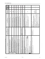
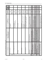
Representative water temperature thermistor (TH14)
High-pressure sensor fault, High-pressure fault
Model setting error 1
Model setting error 2
Power supply frequency fault
Low-pressure sensor fault, Low-pressure fault
5114
5117
5118
7113
7117
●A temperature of -50ºC or below OR 80ºC or above has been detected for 20
seconds or longer while the operation command is on.
●A temperature of -50ºC or below OR 80ºC or above has been detected for 20
seconds or longer while the operation command is on.
●When the operation signal is ON A high-pressure of -0.1 MPa or below (open-circuit)
or 4.0 MPa or above (short-circuit) has been detected for 20 seconds.
●When the operation signal is ON A high-pressure of -0.1 MPa or below (open-circuit)
or 2.0 MPa or above (short-circuit) has been detected for 20 seconds.
●SW1-1, 1-2, 1-3, or 1-4 (model setting) is set to the setting that corresponds to a
model that is not on the model list while the power is turned on.
●SW1-1, 1-2, 1-3, or 1-4 (model setting) is set to the setting that corresponds to a
model that is not on the model list while the power is turned on.
●Dip switches on the circuit board
were set incorrectly at the time of
servicing.
Thermistor fault
●High-pressure input circuit fault on the control board
●Broken or shorted high-pressure sensor wiring
(High-pressure sensor fault, broken sheath, missing connector pins)
●Incorrect SW1 setting on the control board
●Resistor Z21 fault (connected to CNTYP1 on the Main control board)
●Resistor fault (connected to CNTYP2 on the INV board)
●Low-pressure input circuit fault on the control board
●Pressure drop due to refrigerant leakage
●Broken or shorted low-pressure sensor wiring
(Low-pressure sensor fault, broken sheath, missing connector pins)
(Thermistor fault, pinched lead wire, missing pins on the connectors)
●Thermistor input circuit fault on the control board
●Broken or short-circuited thermistor wiring
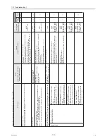
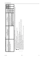
5102
5106
Air-side heat exchanger inlet thermistor fault (TH4 MAIN circuit)
Air-side heat exchanger inlet thermistor fault (TH8 SUB circuit)
5104
5108
●A temperature of -50ºC or below OR 80ºC or above has been detected for 20
seconds or longer while the operation command is on.
Suction refrigerant thermistor fault (TH2 MAIN circuit)
Suction refrigerant thermistor fault (TH6 SUB circuit)
(problem with the installation
environment/setting error)
Circuit board
(Thermistor fault, pinched lead wire, missing pins on the connectors)
●Thermistor input circuit fault on the control board
●Broken or short-circuited thermistor wiring
(Thermistor fault, pinched lead wire, missing pins on the connectors)
●Thermistor input circuit fault on the control board
●Broken or short-circuited thermistor wiring
Cause
(component problem)
Error Code
Remote controller
Resetting the error
Unit side
board)
(Circuit
Remote
SWS1
Operation SW
*Preliminary error codes will not appear on the 7-segment LED.
Error Type
Cause
Summary of Contents for CAHV-P500YA-HPB
Page 1: ...Service Handbook Service Handbook CAHV P500YA HPB Model 2011 HOT WATER HEAT PUMP ...
Page 7: ...CONTENTS HWE10060 GB ...
Page 9: ... 2 HWE10060 GB ...
Page 19: ... 12 HWE10060 GB ...
Page 37: ... 30 HWE10060 GB ...
Page 46: ... 39 HWE10060 GB IV Remote Controller 1 Using the Remote Controller 41 2 Function Settings 46 ...
Page 47: ... 40 HWE10060 GB ...
Page 55: ... IV Remote Controller 48 HWE10060 GB ...
Page 56: ... 49 HWE10060 GB V Electrical Wiring Diagram 1 Electrical Wiring Diagram 51 ...
Page 57: ... 50 HWE10060 GB ...
Page 61: ... V Electrical Wiring Diagram 54 HWE10060 GB ...
Page 63: ... 56 HWE10060 GB ...
Page 67: ... VI Refrigerant Circuit 60 HWE10060 GB ...
Page 69: ... 62 HWE10060 GB ...
Page 101: ... VII Control 94 HWE10060 GB ...
Page 103: ... 96 HWE10060 GB ...
Page 109: ... VIII Test Run Mode 102 HWE10060 GB ...
Page 111: ... 104 HWE10060 GB ...
Page 155: ... IX Troubleshooting 148 HWE10060 GB ...
Page 156: ... 149 HWE10060 GB X Attachments 1 R407C saturation temperature table 151 ...
Page 157: ... 150 HWE10060 GB ...
Page 159: ... X Attachments 152 HWE10060 GB ...


