[
VII
Control ]
- 90 -
HWE10060
GB
2. Normal
Thermo-ON/OFF operations
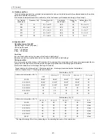
DIFF1 = 2 ºC (Initial setting): “1015” Digitally set value
DIFF2 = 2 ºC (Initial setting): “1016” Digitally set value
Tmax (Outside temperature
≤
-10 ºC: 65ºC, Outside temperature > -10 ºC : 70ºC)
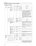
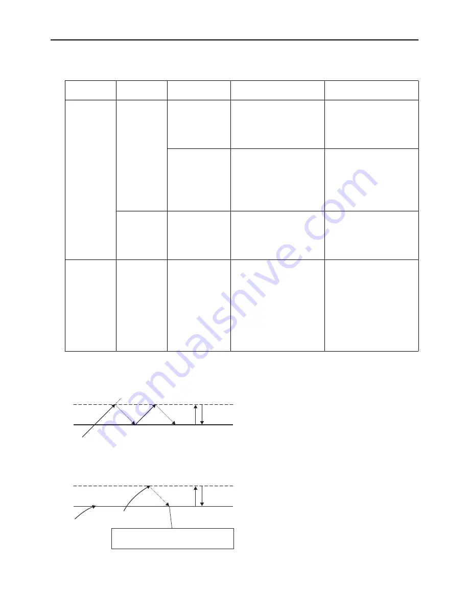
1) Thermo-ON/OFF temperature conditions
Intlet-temperature-based water temperature control in an individual system (with the external water temperature sen-
sor setting being set to ON and the Inlet-/outlet-based control option being set to inlet)
Outlet-temperature-based water temperature control in an individual system (with the external water temperature
sensor setting being set to ON and the Inlet-/outlet-based control option being set to outlet)
Single/Multiple
system
sensor
Thermo-ON
conditions
Thermo-ON
conditions
Thermo-OFF conditions
Individual
system
Built-in
thermistor
Inlet-water-temper-
ature-based control
Inlet water temperatures is low-
er than the "Inlet temperature
at Thermo-OFF - DIFF2ºC"
and the system is not in the
short-cycling protection mode.
Inlet water temperatures are
greater than the "set tempera-
ture + DIFF2 value (ºC)" AND
at least 60 seconds have
passed since the last Thermo-
ON.
Outlet-water-tem-
perature-based
control
Inlet temperatures are below
the "Inlet temperature at Ther-
mo-OFF - DIFF2ºC"AND the
average outlet temperature is
at or below "Preset tempera-
ture + DIFF2ºC" AND the sys-
tem is not in the short-cycling
protection mode.
Average outlet water tempera-
ture is greater than the "set
tempe DIFF2 value
(ºC)" AND at least 60 seconds
have passed since the last
Thermo-ON.
Representative
water
temperature
Water temperature
control based on the
external water tem-
perature reading
Inlet water temperatures is low-
er than the "Inlet temperature
at Thermo-OFF - DIFF2ºC"
External water temperature
sensor reading is greater than
the "set temperature * DIFF2
value (ºC)" AND at least 60
seconds have passed since
the last Thermo-ON.
Multiple
system
Representative
water
temperature
Water temperature
control based on the
external water tem-
perature reading
External water temperature
thermistor reading < Set tem-
perature - DIFF 2 value (ºC)
AND the anti-short-cycling pro-
tection function is not been trig-
gered.
The number of units to run an
optimal operation will be deter-
mined by the main unit.
(The unit with the least amount
of cumulative operation hours
will go into operation first.)
External water temperature
sensor reading is greater than
the "set temperature * DIFF2/2
value (ºC)" AND at least 60
seconds have passed since
the last Thermo-ON.
The number of units to run an
optimal operation will be
determined by the main unit.
(The unit with the least amount
of cumulative operation hours
will go into operation first.)
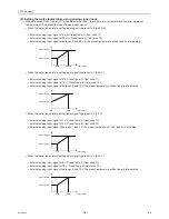
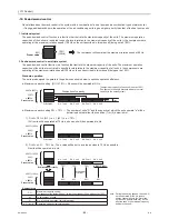
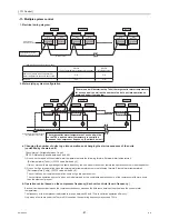
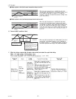
When the water temperature is controlled based on the inlet
temperature, compressor frequency will be controlled as
described in section -3- "Compressor frequency" (page 80).
(Automatic operation according to the preset temperature)
When the water temperature is controlled based on the
external water temperature sensor reading (outlet water
temperature), compressor frequency will be controlled in the
way that the target water temperature will be maintained. If
there is a sudden increase in water temperature and the unit
did not stop at the preset temperature, the unit will stop when
the temperature that equals "the preset tempe the
value set for DIFF2" is reached.
DIFF2°C
Thermo-OFF temperature
Preset water temperature
Inlet water
temperature changes
DIFF2°C
Outlet water temperature
changes 1
Outlet water temperature
changes-2
The unit will restart when the inlet water temperature
drops from the inlet temperature at the time of
Thermo-OFF by more than the value set for DIFF2.
Thermo-OFF temperature
Preset water
temperature
Summary of Contents for CAHV-P500YA-HPB
Page 1: ...Service Handbook Service Handbook CAHV P500YA HPB Model 2011 HOT WATER HEAT PUMP ...
Page 7: ...CONTENTS HWE10060 GB ...
Page 9: ... 2 HWE10060 GB ...
Page 19: ... 12 HWE10060 GB ...
Page 37: ... 30 HWE10060 GB ...
Page 46: ... 39 HWE10060 GB IV Remote Controller 1 Using the Remote Controller 41 2 Function Settings 46 ...
Page 47: ... 40 HWE10060 GB ...
Page 55: ... IV Remote Controller 48 HWE10060 GB ...
Page 56: ... 49 HWE10060 GB V Electrical Wiring Diagram 1 Electrical Wiring Diagram 51 ...
Page 57: ... 50 HWE10060 GB ...
Page 61: ... V Electrical Wiring Diagram 54 HWE10060 GB ...
Page 63: ... 56 HWE10060 GB ...
Page 67: ... VI Refrigerant Circuit 60 HWE10060 GB ...
Page 69: ... 62 HWE10060 GB ...
Page 101: ... VII Control 94 HWE10060 GB ...
Page 103: ... 96 HWE10060 GB ...
Page 109: ... VIII Test Run Mode 102 HWE10060 GB ...
Page 111: ... 104 HWE10060 GB ...
Page 155: ... IX Troubleshooting 148 HWE10060 GB ...
Page 156: ... 149 HWE10060 GB X Attachments 1 R407C saturation temperature table 151 ...
Page 157: ... 150 HWE10060 GB ...
Page 159: ... X Attachments 152 HWE10060 GB ...

