[
IX
Troubleshooting ]
- 112 -
HWE10060
GB
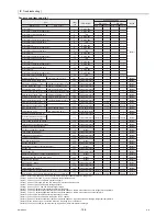
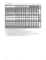
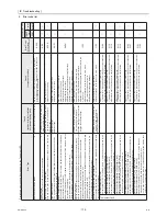
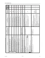
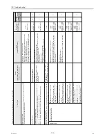
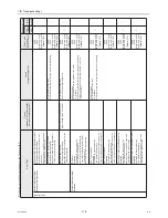
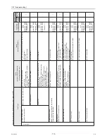
Maintenance item (1) list
Item
code
Incre-
ments
Lower
limit
Upper
limit
Default
Switch
setting
timing
Unit type
Notes
Main unit
Sub unit
MAIN circuit SUB circuit MAIN circuit SUB circuit
Forcing the units in a specific system to stop
1004
1
0
3
0
○
-
○
-
(Note1)
Outlet water temperature sensor correction (hot water)TH11
1009
-
-
-
-
-
○
-
○
-
(Note2)
Outlet water temperature sensor correction (hot water)TH13
1010
-
-
-
-
-
-
○
-
○
Inlet water temperature sensor correction (hot water)TH10
1011
-
-
-
-
-
○
-
○
-
Start/End time setting 1 Water temp setting
1
1
3
1
○
-
-
-
Start/End time setting 2 Water temp setting
1218
1219
1220
1
1
3
1
○
-
-
-
Start/End time setting 3 Water temp setting
1
1
3
1
When unit is stopped
When unit is stopped
When unit is stopped
When unit is stopped
When unit is stopped
When unit is stopped
When unit is stopped
When unit is stopped
When unit is stopped
○
-
-
-
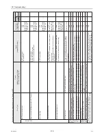
Inlet water temperature sensor correction (hot water)TH12
1012
-
-
-
-
-
-
○
-
○
Representative water temperature sensor correction
(hot water)TH14
1013
-
-
-
-
-
○
-
-
-
Representative water temperature sensor correction
(hot water)TH15
1014
-
-
-
-
-
○
-
-
-
Built-in thermistor differential DIFF1
1015
-
-
-
-
-
○
○
○
○
(Note3)
Built-in thermistor differential DIFF2
1016
-
-
-
-
-
○
○
○
○
Cumulative operation time of the compressor
1017
-
-
-
-
Can be reset
only when unit
is stopped
○
○
○
○
(Note4)
(Note5)
(Note6)
Cumulative operation time of the compressor
(Unit: 10,000 hours)
1018
-
-
-
-
Can be reset
only when unit
is stopped
○
○
○
○
(Note4)
(Note5)
(Note6)
(Note7)
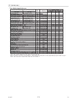
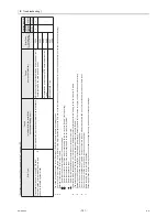
Temperature data collection interval (S seconds)
1019
1 second
1
9999
60
○
○
○
○
(Note8)
Multiple system Thermo-ON/OFF status check interval
1020
1 minute
1
5
1
○
-
-
-
(Note9)
1215
1
14
15
14
○
-
-
-
Representative water temperature thermistor while the
"Temperature shift (Setting temperature B)" function is enabled.
Representative water temperature thermistor while the
"Temperature shift (Setting temperature A)" function is enabled.
1216
1
14
15
14
○
-
-
-
(Note10)
Representative water temperature thermistor while the
"Temperature shift (Setting temperature C)" function is enabled.
1217
1
14
15
14
○
-
-
-
(Note11)
(Note1) Do not use this item. (Stop the units in a given system by setting the slide switch SWS1 to OFF.)
(Note2) Consult your nearest Mitsubishi representative if the sensors go off below the preset values.
(Note3) Consult your nearest Mitsubishi representative.
(Note4) These items can only be displayed. (Their settings cannot be changed.)
(Note5) The cumulative time between 1 and 9999 hours will be displayed in four digits. (unit: hour)
(Note6) Pressing the push switches SW01 and SW02 simultaneously while the time is displayed will reset (initialize) the data to 0.
(Note7) The cumulative time between 10,000 and 99,990,000 hours will be displayed in four digits (unit: 10000 hours)
(Note8) Set the data collection interval by referring to section “3. Operation status before error”. (Page 109)
(Note9) The Thermo-ON/OFF status check interval can be adjusted to optimize the ON/OFF operation when the piping length to the load side is long and the
detection of changes in water temperature tends to lag behind.
(Note10) Set these settings when using both external thermistors TH14 and TH15 and switching between the two according to the preset water temperature.
(Heating temperature = A°C, Hot water temperature = B °C, Heating ECO temperature = C °C)
(Note11) Set these settings when changing the temperature settings for the units by using the schedule function of the control board.
(Heating temperature: 1
Hot water temperature: 2, Heating ECO temperature: 3)
Summary of Contents for CAHV-P500YA-HPB
Page 1: ...Service Handbook Service Handbook CAHV P500YA HPB Model 2011 HOT WATER HEAT PUMP ...
Page 7: ...CONTENTS HWE10060 GB ...
Page 9: ... 2 HWE10060 GB ...
Page 19: ... 12 HWE10060 GB ...
Page 37: ... 30 HWE10060 GB ...
Page 46: ... 39 HWE10060 GB IV Remote Controller 1 Using the Remote Controller 41 2 Function Settings 46 ...
Page 47: ... 40 HWE10060 GB ...
Page 55: ... IV Remote Controller 48 HWE10060 GB ...
Page 56: ... 49 HWE10060 GB V Electrical Wiring Diagram 1 Electrical Wiring Diagram 51 ...
Page 57: ... 50 HWE10060 GB ...
Page 61: ... V Electrical Wiring Diagram 54 HWE10060 GB ...
Page 63: ... 56 HWE10060 GB ...
Page 67: ... VI Refrigerant Circuit 60 HWE10060 GB ...
Page 69: ... 62 HWE10060 GB ...
Page 101: ... VII Control 94 HWE10060 GB ...
Page 103: ... 96 HWE10060 GB ...
Page 109: ... VIII Test Run Mode 102 HWE10060 GB ...
Page 111: ... 104 HWE10060 GB ...
Page 155: ... IX Troubleshooting 148 HWE10060 GB ...
Page 156: ... 149 HWE10060 GB X Attachments 1 R407C saturation temperature table 151 ...
Page 157: ... 150 HWE10060 GB ...
Page 159: ... X Attachments 152 HWE10060 GB ...

