[
VII
Control ]
- 89 -
HWE10060
GB
Cooling/heating Circuit Control and General Function of System Equipment
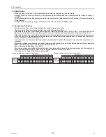
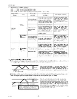
-13- Water-temperature control
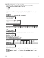
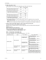
Water temperature can be controlled in the following three ways. Select one that works best.
*1 When dip switch SW2-8 is set to ON, the ON/OFF operation of the units is controlled based on the external water
temperature sensor reading.
How the operating frequency of the compressor is controlled depends on the SW3-3 setting (outlet-/inlet-based control
option).
(Sub units will be controlled based on the water-temperature control method that has been selected for the Main unit.)
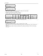
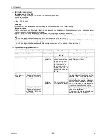
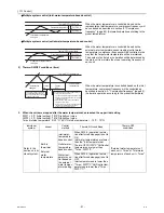
1. When the units are restarted after stopping for under a condition other than Thermo-OFF
Conditions for the units to stop other than the Thermo-OFF condition
The control option was changed from built-in thermistor reading based control to the external thermistor reading based
control.
Pump interlock is off.
When one of the units in a set is forced to stop
When the Capacity priority/Cop priority setting was changed.
When the units were stopped under the following conditions:
1. Tmax has reached 65ºC (when the outside temperature
≤
-10ºC) or
2. Tmax has reached 70ºC (when the outside temperature > -10ºC.
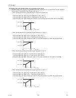
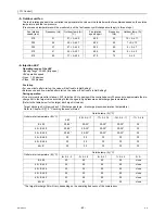
DIFF1 = 2 ºC (Initial setting): “1015” Digitally set value
DIFF2 = 2 ºC (Initial setting): “1016” Digitally set value
Tmax (Outside temperature
≤
-10 ºC: 65ºC, Outside temperature > -10 ºC : 70ºC)
Switch Factory
setting
Outlet-water-temperature-based control
SW3-3
OFF
Inlet-water-temperature-based control
-
Water temperature control based on the
external water temperature reading
SW2-8
OFF
SW3-3
SW2-8
Outlet-water-temperature-based control
OFF
OFF
Inlet-water-temperature-based control
ON
OFF
Water temperature control based on the
external water temperature reading
Arbitrary
*1
ON
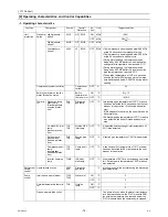
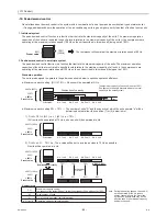
Single/Multiple system
sensor
Control method
Thermo-ON conditions
Individual system
Built-in thermistor
Inlet-water-tempera-
ture-based control
Outlet water temperatures
< (Preset water temperature - DIFF1ºC)
AND
Inlet water temperatures
< (Preset water temperature - DIFF1ºC)
Outlet-water-temper-
ature-based control
Outlet water temperatures
< (Preset water temperature - DIFF1ºC)
AND
Inlet water temperatures
< (Preset water temperature - DIFF1ºC)
AND
Average outlet water temperature
≤
(Preset water temp DIFF2ºC)
Representative water
temperature
Representative water
temperature
Representative water temperature
< (Preset water temperature - DIFF1ºC)
Multiple system
Representative water
temperature
Representative water
temperature
Representative water temperature
< (Preset water temperature - DIFF2/2)
AND
The number of units to run an optimal opera-
tion will be determined by the main unit.
(The unit with the least amount of cumulative
operation hours will go into operation first.)
Summary of Contents for CAHV-P500YA-HPB
Page 1: ...Service Handbook Service Handbook CAHV P500YA HPB Model 2011 HOT WATER HEAT PUMP ...
Page 7: ...CONTENTS HWE10060 GB ...
Page 9: ... 2 HWE10060 GB ...
Page 19: ... 12 HWE10060 GB ...
Page 37: ... 30 HWE10060 GB ...
Page 46: ... 39 HWE10060 GB IV Remote Controller 1 Using the Remote Controller 41 2 Function Settings 46 ...
Page 47: ... 40 HWE10060 GB ...
Page 55: ... IV Remote Controller 48 HWE10060 GB ...
Page 56: ... 49 HWE10060 GB V Electrical Wiring Diagram 1 Electrical Wiring Diagram 51 ...
Page 57: ... 50 HWE10060 GB ...
Page 61: ... V Electrical Wiring Diagram 54 HWE10060 GB ...
Page 63: ... 56 HWE10060 GB ...
Page 67: ... VI Refrigerant Circuit 60 HWE10060 GB ...
Page 69: ... 62 HWE10060 GB ...
Page 101: ... VII Control 94 HWE10060 GB ...
Page 103: ... 96 HWE10060 GB ...
Page 109: ... VIII Test Run Mode 102 HWE10060 GB ...
Page 111: ... 104 HWE10060 GB ...
Page 155: ... IX Troubleshooting 148 HWE10060 GB ...
Page 156: ... 149 HWE10060 GB X Attachments 1 R407C saturation temperature table 151 ...
Page 157: ... 150 HWE10060 GB ...
Page 159: ... X Attachments 152 HWE10060 GB ...

