[
V
Electrical Wiring Diagram ]
- 51 -
HWE10060
GB
V
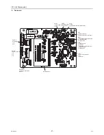
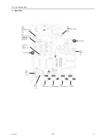
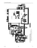
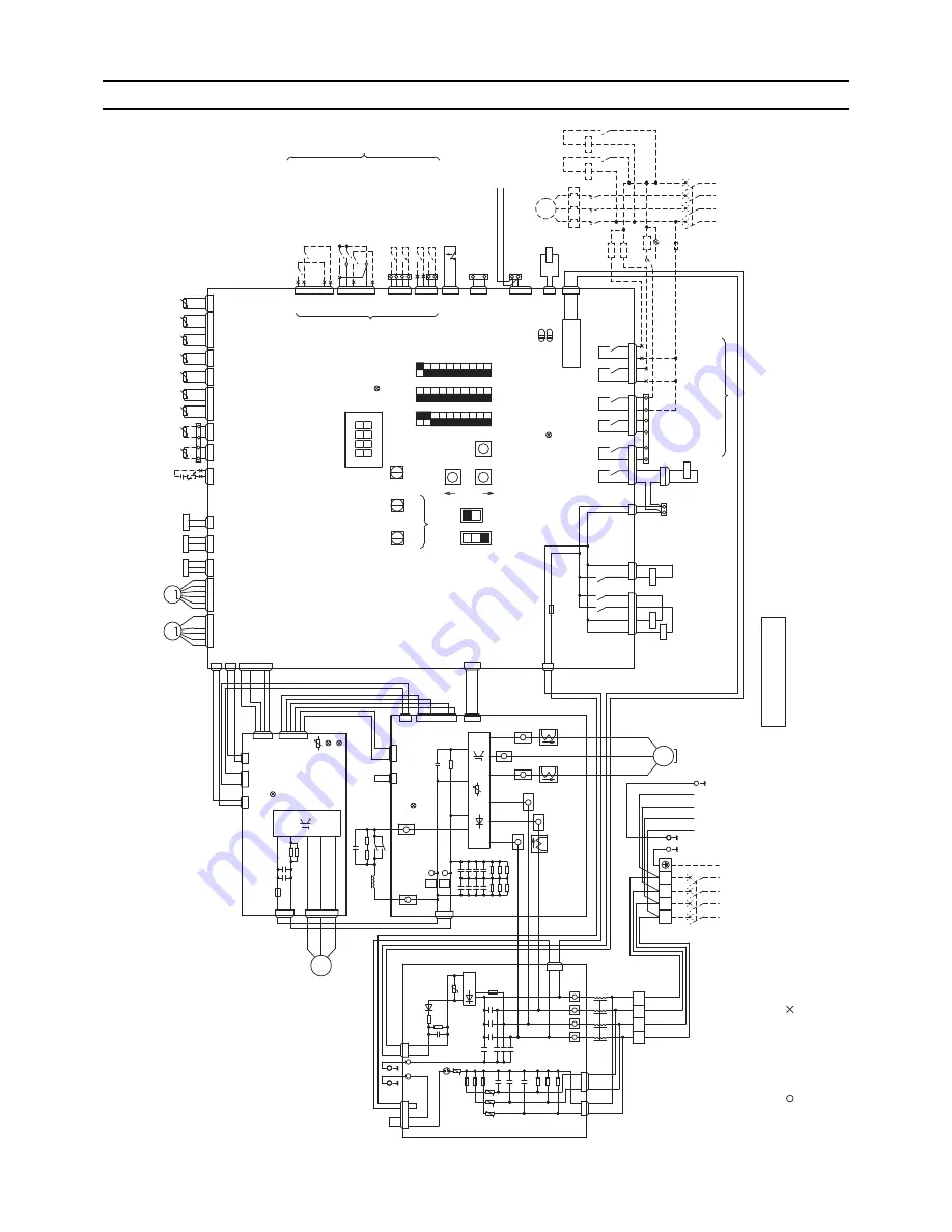
Electrical Wiring Diagram
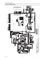
[1] Electrical Wiring Diagram
SW421
OFF
O
N
1
2
5 4
6
2 1
3
5 4
6
3
1
2
34
76
5
3
21
4
L3
L2
L1
N
L3
L2
L1
N
1
2
3
4
5
6
4
1
2
3
12
2
13
1
2
4
1
3
2
12
34
56
7
3
2
1
41
2
3
21
3
6
5
4
12
3
1
2
3
12
34
13
2
2
1
1
2
7
2
3
4
1
5
6
1
2
1
2
3
1
2
3
41
2
3
5
6
7
1
2
1
2
3
4
1
2
3
2
3
4
5
76
1
12
4
2 1
3
2 1
3
1
2
5
1
6
3
26
4
3
1
2
4
5
56
4
54
3
3
2
2
2
1
1
3
2
1
1
1
3
1
13
11
4
1
2
22
3
2
2
3
4
2
2
2
1
3
1
7
2
6
1
12
3
4
2
1
3
1
2
Control Board
(ON/OFF)
CN142D
blue
CN142C
Flow switch
Mode change1
Capacity mode
Demand
Anti freeze
23
24
External
Water sensor
.2
CN406
yellow
T3
T4
°
TH15
t
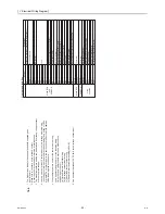
Note1.Single-dotted lines indicate field wiring.
Note2.The symbols of the field connecting terminals are as follows.
:T
erminal block :Connection by cutting the short circuit wire
Note3.Faston terminals have a locking function.
Press the tab in the middle of the terminals to remove them.
Check that the terminals are securely locked in place after insertion.
power supply
3N~
50Hz
380/400/415V
power supply 3N~ 50Hz 380/400/415V
yellow CN512
No-V
oltage
contact input
(COP
priority/
Capacity priority)
(ON/OFF)
H21
H20
(ON/OFF)
10' digit
1' digit
External
Water sensor
.1
N
X21
X20
X21
X20
Drain pan
heater
Emargency
signal
(for extra
heater)
X09
X08
(Normal/Error)
(Normal/Error)
(Hot water/ Heating)
(coercion/ by ordinary)
(Heating Eco/ Heating)
Mode change2
(ON/OFF)
Pump interlock
Fan mode
Run
R
un/Stop
Air hex Ref
temp.1
Water temp.setting
Analog input
4~20mA
Error display output
Operation display
output
Suction Ref
temp.1
Discharge Ref
temp.1
N
72C
DC12V
MAIN BOX
Pump operation
command output
X04
X05
X06
X07
70
CNAC
red
To
SUB BOX
TB4
L1
L2
L3
A
B
CN102
MA
MB
CN3A
blue
RA
RB
No-voltage contact output
SV2
73
72
71
75
74
CN510
blue CN51
1
Z21
t
TH14
TH2
TO
SUB BOX
TB3
CN63LS
red
3
CN405
blue
X01
CN402
green
X02
CN404
black
X03
CN401
CN502
CN501
CH
pump error
CN142B
blue
SV1
°
21S4
51P
52P
ELB2
MP
L2
CN801
yellow
LED2:CPU in operation
Tr
ansmission cable for multiple unit control
Measurement terminal for maintenance(M-NET)
M
(+)
TH3
(-)
T2
T1
4
5
CN63HS
2
6
7
LEV1
8
15
1
PL
16
19
20
CNL
VC
blue
11
12
L1
SW1
52P
SW2
SW3
ON
Outdoor temp.1
OFF
ON
OFF
Shell Ref temp.1
ON
TB2
LED1
LED3:Lit while
energized
9
10
1
2
10
10
9
8
7
6
5
4
3
black
CNAC2
1
M
3
4
5
(0)
LEV2
6
7
8
9
ENTER
Optional remote controller connecting terminal (Non-polarized)
SWP2
Unit address setting
SWP3
(0)
SWU1
UP
(1)
SWP1
SWU2
DOWN
SWU3
B
A
OFF
Water outlet
temp.1
LOCAL
SWS1
SWS2
L3
CN142A
black
CN408
CN2
F06 AC250V 3.15A
T
CN4CN332
blue
Water inlet
temp.1
TB1
CN421
black
62
2
66
CNL
VA
°
CN407
red
°°
°°
°°
OFF
t
tt
tt
tt
63H1
F2
REMOTE
63LS
63HS
ELB1
TH9
TH4
TH1
TH10
TH1
1
Contorol power circuit
CNTYP1
black
The specification of the product is for the improvement
a previous notice and might change.
TB5
TB6
TB6
TB6
TB5
TB6
TB6
TB6
TB5
CNTYP2
U
W
V
MS 3~
red
white
black
Motor
(Compressor)
CNDC Pink
CN52C red
C5
Z5
C3
C2
F02
R01
R02
F01
R03
Z1
Z2
R34
C30
C32
C34
C36
black
F03
F04 AC250V 6.3A
T
black
white
L
F01,F02,F03 AC250V 6.3A
T
DSA
R35
CT3
white
R33
SC-L3
R30
red
w
hite
D1
R04
R32
R06
CN2
C31
CN18V blue
U
Z4
C17
CN4 red
TB21
CN1B
L1
CN1A
red
Noise Filter
TB22
CN3 green
TB24
Fan motor (Heat exchanger)
N
C33
TB23
IPM
FA
N Board
F05 DC700V 4A
T
*4
black
U
red
Diode Bridge
2
72C
1
black
SC-P2
C7
C8
CT12
L2
R5
U
LED1:Normal
operation
+
red
C35
DCL
SC-L2
SC-P1
SC-U
CN1
black
C37
CN5V yellow
C1
C9
C10
CN6
4
C100
LED1:Normal operation(lit)
/ Error(blink)
LED3:CPU in
operation
R1
CN4
CN2
SC-V
U
IGBT
CT22
U
CNINV
SC-W
SC-L1
W
CN21 blue
U
CNVDC
CN4 blue
C631
°
LED2:Error
R630
R631
CN22 red
t
Z3
CN5
R31
C6
CNTYP black
C1
RSH1
THHS
t
FT
-P
P
N
°
FT
-N
C4
+
INV Board
+
C630
+
+
+
+
+
+
3
red
L3
THBOX
-
+
V
M 3~
M 3~
Summary of Contents for CAHV-P500YA-HPB
Page 1: ...Service Handbook Service Handbook CAHV P500YA HPB Model 2011 HOT WATER HEAT PUMP ...
Page 7: ...CONTENTS HWE10060 GB ...
Page 9: ... 2 HWE10060 GB ...
Page 19: ... 12 HWE10060 GB ...
Page 37: ... 30 HWE10060 GB ...
Page 46: ... 39 HWE10060 GB IV Remote Controller 1 Using the Remote Controller 41 2 Function Settings 46 ...
Page 47: ... 40 HWE10060 GB ...
Page 55: ... IV Remote Controller 48 HWE10060 GB ...
Page 56: ... 49 HWE10060 GB V Electrical Wiring Diagram 1 Electrical Wiring Diagram 51 ...
Page 57: ... 50 HWE10060 GB ...
Page 61: ... V Electrical Wiring Diagram 54 HWE10060 GB ...
Page 63: ... 56 HWE10060 GB ...
Page 67: ... VI Refrigerant Circuit 60 HWE10060 GB ...
Page 69: ... 62 HWE10060 GB ...
Page 101: ... VII Control 94 HWE10060 GB ...
Page 103: ... 96 HWE10060 GB ...
Page 109: ... VIII Test Run Mode 102 HWE10060 GB ...
Page 111: ... 104 HWE10060 GB ...
Page 155: ... IX Troubleshooting 148 HWE10060 GB ...
Page 156: ... 149 HWE10060 GB X Attachments 1 R407C saturation temperature table 151 ...
Page 157: ... 150 HWE10060 GB ...
Page 159: ... X Attachments 152 HWE10060 GB ...

