1-22
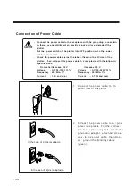
Connection of Power Cable
• Connect the power cable to the receptacle with the grounding connection,
or there are possibilities of an electric shock and/or a damage of the
plotter.
• Put the power switch of the plotter into OFF position when the power
cable is connected.
• Check the power cable against the label affixed on the AC inlet of the
plotter. Then, connect the power cable to a receptacle with the following
specifications.
Domestic/Overseas 100V
Overseas 200 V
Voltage
: AC100-120V
±
10%
Voltage
: AC200-240V
±
10%
Frequency : 50/60Hz
±
1%
Frequency : 50/60Hz
±
1%
Current
: 1.5A and over
Current
: 0.75A and over
1
Connect the power cable to the
power inlet of the plotter.
2
Connect the power cable to a 3 pins
power receptacle. For the connec-
tion to a 2 pins receptacle, install the
grounding adapter, attached acces-
sory, to the power cable, then prop-
erly ground the bonding cable
( g r e e n ) .
In the case of 3 pins receptacle
In the case of 2 pins receptacle
Summary of Contents for cg-100AP
Page 16: ...xiv ...
Page 70: ...1 54 ...
Page 108: ...2 38 ...
Page 145: ...CHAPTER 4 SELF DIAGNOSIS FUNCTION 4 9 DEMONSTRATION PATTERN 1 2 Demonstration Pattern 1 ...
Page 146: ...4 10 Demonstration Pattern 2 ...
Page 173: ...CHAPTER 6 APPENDIX 6 13 Table of 82 special character codes supported ...
Page 179: ...D200310MAC 2 00 09061999 ...
Page 180: ... MIMAKI ENGINEERING CO LTD 1999 6 Printed in japan ...


