CHAPTER 1
SET-UP
1-13
9
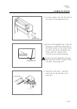
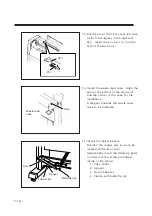
Plug the rubber caps into the holes of
the stand for the tightened bolts.
1 0 Position the elongated hole of the roll
stay assy. so that the screw hole of
the stand comes at the nearly center
portion of the above elongated hole.
Secure with four butterfly bolts
(Left hand: 2ea, Right hand:2ea)
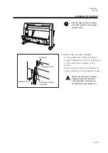
Be sure to finely adjust the roll stays
after placing a sheet of paper on the
roll stays. (See page 2-8.)
1 1 Install the front cover. Insert the
right side pin into the hole of the
main unit.
Rubber cap
Front cover
ASSEMBLY OF PLOTTER
Elongated hole
Summary of Contents for cg-100AP
Page 16: ...xiv ...
Page 70: ...1 54 ...
Page 108: ...2 38 ...
Page 145: ...CHAPTER 4 SELF DIAGNOSIS FUNCTION 4 9 DEMONSTRATION PATTERN 1 2 Demonstration Pattern 1 ...
Page 146: ...4 10 Demonstration Pattern 2 ...
Page 173: ...CHAPTER 6 APPENDIX 6 13 Table of 82 special character codes supported ...
Page 179: ...D200310MAC 2 00 09061999 ...
Page 180: ... MIMAKI ENGINEERING CO LTD 1999 6 Printed in japan ...

