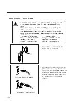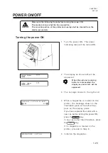
1-20
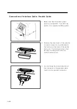
Connection of Interface Cable: Parallel Cable
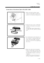
1
Make sure that the plotter power
switch is turned OFF. Turn OFF the
switch if it is selected at ON position.
2
Remove the dust cover of the parallel
connector (option to be embodied in
the factory) at the back of the plotter
main unit. The removed cover shall
be kept in storage with other at-
t a c h e d a c c e s s o r i e s .
3
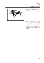
As confirming the correct direction of
the connector of the parallel cable,
insert into the parallel connector.
Summary of Contents for cg-100AP
Page 16: ...xiv ...
Page 70: ...1 54 ...
Page 108: ...2 38 ...
Page 145: ...CHAPTER 4 SELF DIAGNOSIS FUNCTION 4 9 DEMONSTRATION PATTERN 1 2 Demonstration Pattern 1 ...
Page 146: ...4 10 Demonstration Pattern 2 ...
Page 173: ...CHAPTER 6 APPENDIX 6 13 Table of 82 special character codes supported ...
Page 179: ...D200310MAC 2 00 09061999 ...
Page 180: ... MIMAKI ENGINEERING CO LTD 1999 6 Printed in japan ...

