1-18
CONNECTION OF CABLES
General Description
• Connect the interface cable first and the power cable next in order.
• Use the interface cable specified by this COMPANY only.
• Turn off the power of the plotter and host computer
Connect the following two cables so as to operate the UNIT.
Prepare the interface cable specified by this COMPANY and the attached power cable.
1
Connect the UNIT with the host computer. ---> Interface cable
2
Supply the power
---> Power cable
Interfaces
The UNIT equips with the RS-232C interface as the standard component
A parallel interface is also prepared as an optional component.
Please use the interface applicable to the specification of the host computer and application software. The inter-
face connector is located at the back of the main unit.
RS-232C interface:
It is necessary to establish the condition (communication condition) such as the datatransfer rate
for using this interface. Establish the communication condition in accordance with the
specification of the internal software of the host computer and application software.
Parallel interface:
Since the specification of this interface is almost unified, this interface can be connected without
setting the communication condition.
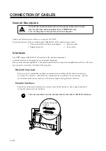
• The communication can be achieved faster than that of RS-232C interface.
Parallel connector
(option)
RS-232C connector
Summary of Contents for cg-100AP
Page 16: ...xiv ...
Page 70: ...1 54 ...
Page 108: ...2 38 ...
Page 145: ...CHAPTER 4 SELF DIAGNOSIS FUNCTION 4 9 DEMONSTRATION PATTERN 1 2 Demonstration Pattern 1 ...
Page 146: ...4 10 Demonstration Pattern 2 ...
Page 173: ...CHAPTER 6 APPENDIX 6 13 Table of 82 special character codes supported ...
Page 179: ...D200310MAC 2 00 09061999 ...
Page 180: ... MIMAKI ENGINEERING CO LTD 1999 6 Printed in japan ...

