


2-59
6.3 INSPECTION AND ADJUSTMENT
[1] Parts inspection
Subject area
Judgment criteria
Remedy
・
Housing
・
Block body
・
Scratch and blemish, stain or corrosion of spool sliding area
・
Scratch and blemish, stain or corrosion of the seal pocket of
spool insertion area
・
Scratch and blemish, stain or corrosion of the port seal in
contact with the O-ring
・
Scratch and blemish, stain or corrosion of the sealing area of
relief valve
・
Any other damage that may spoil normal functions
・
Replacement
・
Replacement
・
Replacement
・
Replacement
・
Replacement
・
Spool
・
Scar that catches a finger nail of the circumferential sliding
surface when touched
・
Blemishes on the sliding surface mating with an end seal
・
Spool action is not smooth.
・
Replacement
・
Replacement
・
Repair or replace
・
Load check valve
・
Imperfect sealing due to damage of valve or spring
・
When inserted in a block body and allowed to operate, it
should move smoothly without being caught.
・
Repair or replace
・
Normal
・
Spring and its periphery
・
Significant damage such as stain, corrosion, deformation or
breakage of spring, holder, and cover
・
Replacement
・
Spool sealing area
・
Outward oil leakage
・
Stain, corrosion or deformation of seal holder
・
Repair or replace
・
Repair or replace
・
Main relief valve
・
Port relief valve
・
Anti-cavitation valve
・
Stain or damage in appearance
・
Damage on the valve seat mating surface
・
Damage on the poppet mating surface
・
Fault in spring
・
O-ring, backup ring, and seals
・
Replacement
・
Replacement
・
Replacement
・
Replacement
・
Total replacement
is required in
principle.
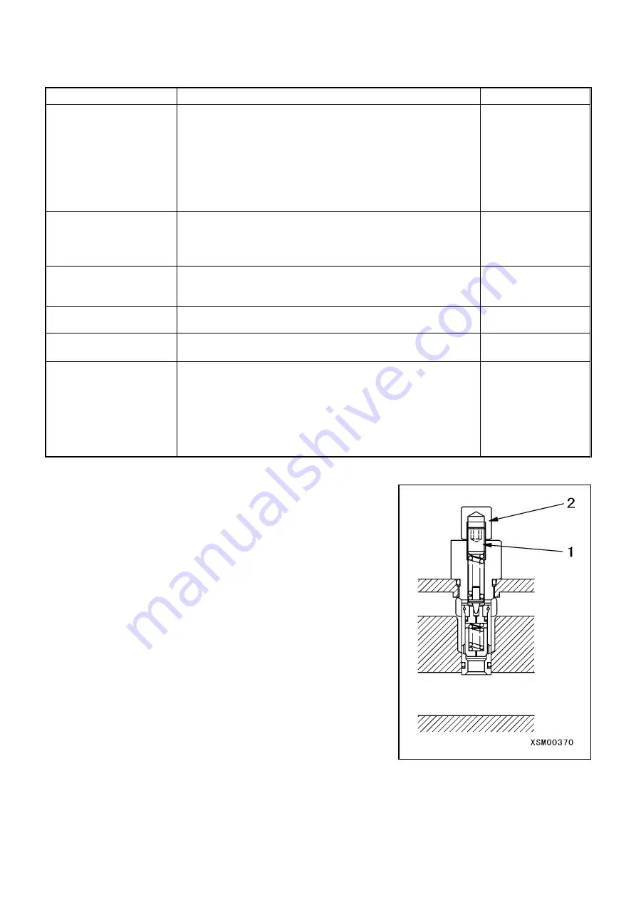
[2] Pressure adjustment of main relief valve
1. Attach a pressure gauge to the pressure detection port.
2. Run the pump at its rated revolution speed.
3. Allow the control valve spool to move to its full stroke and read the
pressure gauge value.
4. Loosen the lock nut (2) of main relief valve.
5. While watching the pressure gauge, turn set screw (1) to adjust the
pressure.
・
Clockwise direction (turning rightward): To raise the set
pressure.
・
Counterclockwise direction (turning leftward):
To lower the set pressure.
6. After completing the pressure adjustment, tighten the lock nut (2)
while preventing the set screw (1) from turning.
7. Run the pump again at its rated revolution speed to ensure that the
pressure is stabilized.
Summary of Contents for MK0003
Page 2: ......
Page 8: ...0 6...
Page 12: ...1 4 2 DIMENSIONAL DRAWING OF OUTRIGGER WIDTH...
Page 17: ...1 9 4 WORKING RADIUS LIFTING HEIGHT...
Page 18: ...1 10 Working range diagram Outrigger extended to maximum Main boom 1 section...
Page 19: ...1 11 Working range diagram Outrigger extended to maximum Main boom 2 sections...
Page 20: ...1 12 Working range diagram Outrigger extended to maximum Main boom 2 5 sections...
Page 21: ...1 13 Working range diagram Outrigger extended to maximum Main boom 3 sections...
Page 22: ...1 14 Working range diagram Outrigger extended to minimum Main boom 1 section...
Page 23: ...1 15 Working range diagram Outrigger extended to minimum Main boom 2 sections...
Page 24: ...1 16 Working range diagram Outrigger extended to minimum Main boom 2 5 sections...
Page 25: ...1 17 Working range diagram Outrigger extended to minimum Main boom 3 sections...
Page 26: ...1 18 5 RATED TOTAL LOAD CHART...
Page 32: ...2 4...
Page 33: ...2 5 1 HYDRAULIC CIRCUIT DIAGRAM 200 1176600...
Page 34: ...2 6...
Page 35: ...2 7 2 HYDRAULIC PIPING DIAGRAM 2 1 CRANE ROTATING PART 200 1171800...
Page 41: ...2 13 2 2 CONTROL LINE A...
Page 43: ...2 15 2 3CONTROL LINE B Perform spiral winding on the entire perimeter of the hose of this part...
Page 45: ...2 17 2 4 TRAVEL LINE...
Page 47: ...2 19 2 5 OUTRIGGER LINE...
Page 49: ...2 21 2 6 PT LINE 102 1152000 4...
Page 69: ...2 41...
Page 70: ...2 42...
Page 71: ...2 43...
Page 76: ...2 48 4 8 ENGINE ACCESSORIES 102 1149200...
Page 90: ...2 62 7 2 INTERNAL STRUCTURE...
Page 120: ...2 92 Part B Writing method for wire number Two places...
Page 123: ...2 95 Figure 1 Index point Figure 2 Connection diagram...
Page 166: ...2 138 15 4 APPEARANCE OF OUTRIGGER ON REAR LEFT SIDE 200 2167300...
Page 173: ...2 145 17 ELECTRIC CIRCUIT DIAGRAM 200 1176500 01...
Page 174: ...2 146 18 ELECTRIC SYSTEM 18 1 1 WIRE HARNESS OF MACHINE BODY 1 200 1172200 1...
Page 176: ...2 148 18 1 2 WIRE HARNESS OF MACHINE BODY 2 200 1172200 2...
Page 179: ...2 151 19 CONTROL ASSEMBLY 19 1 CONTROLLER 1 TTC60 Pin arrangement...
Page 180: ...2 152 TTC60 I O...
Page 181: ...2 153 2 TTC36X Pin arrangement...
Page 182: ...2 154 TTC36X lower part I O...
Page 209: ...2 181 19 2 5 LIST OF CONTROLLER INPUT MONITORING...
Page 210: ...2 182 19 2 6 LIST OF CONTROLLER ANALOG INPUT OUTPUT MONITORING...
Page 245: ...3 9 1 2 3 ANGLE METER 360 S200M3297000...
Page 274: ...3 38...
Page 293: ...4 19 8 SERVICE LOCATIONS...
Page 294: ...4 20...
Page 296: ...5 2 1 ELECTRICAL MOTOR UNIT ASSEMBLY Unit weight 180 kg...
Page 324: ...5 30...
Page 325: ...5 31 4 ELECTRICAL DIAGRAM S200M3122000 01...
Page 326: ...5 32 S200M3122000 02...
Page 336: ...6 8 1 3 2 INTERNAL STRUCTURE OF WINCH MOTOR...
Page 345: ...6 17 4 WORKING RADIUS LIFTING HEIGHT OF ONE FALL WINCH...
Page 348: ......