


2-158
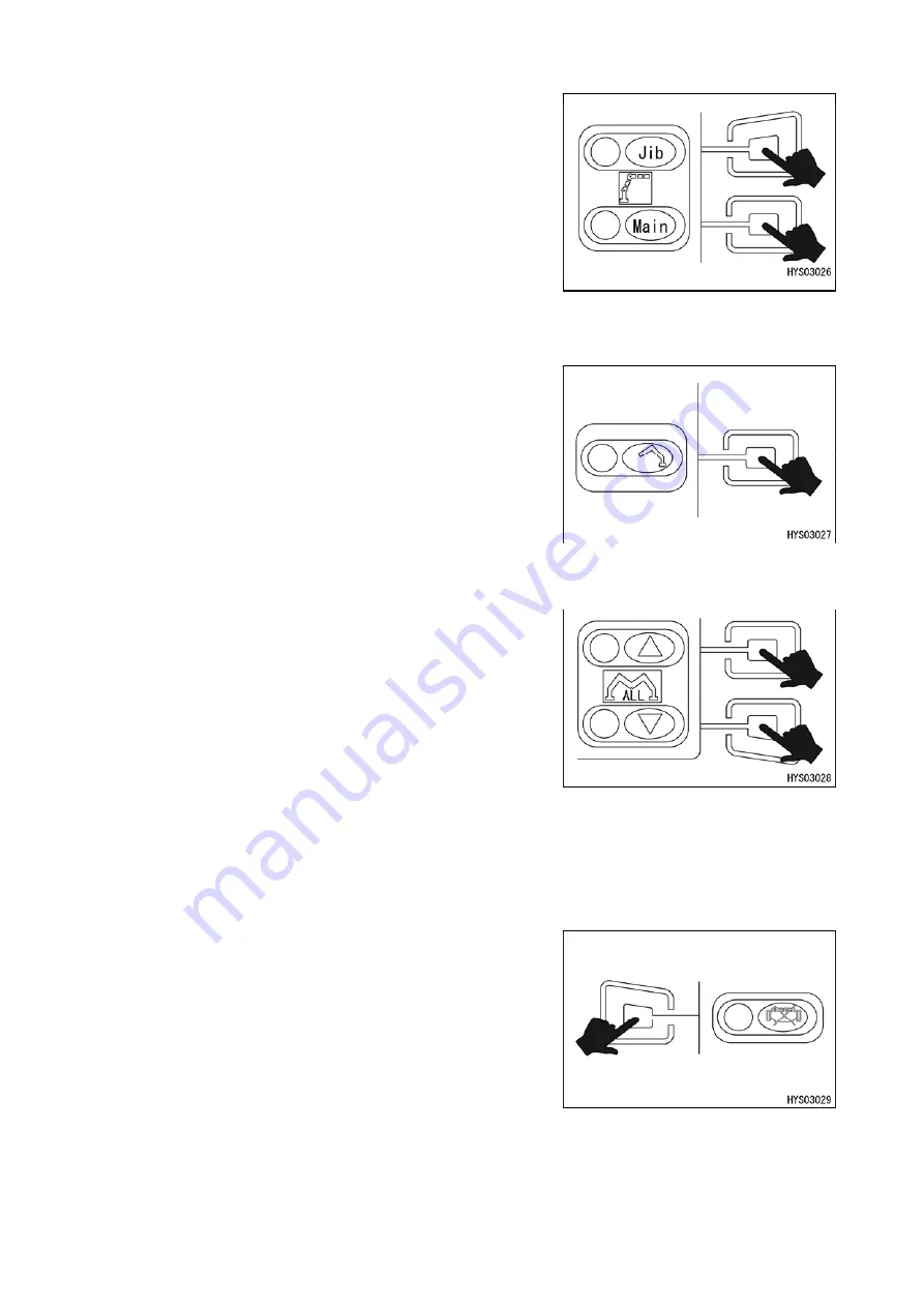
(1) Selector button
(1-1) Jib selector button
Use this switch to change between the jib and main boom.
When the jib selector button is pressed, the display on the left turns
from blue to green and the jib is selected.
(1-2) Main boom selector button
Use this switch to change between the main boom and jib.
When the main boom selector button is pressed, the display on the
left turns from blue to green and the main boom is selected.
(1-3) Individual outrigger operation selector button
Use this button to change to the outrigger individual operation mode.
When “Individual outrigger operation selector button” is pressed, the
screen changes to the outrigger individual operation screen of the
monitor 3.
(1-4) Collective outrigger (ON) button
Use this switch to operate the 4 outriggers simultaneously.
When “Collective outrigger (ON) button” is pressed, the four
outrigger cylinders contract simultaneously and the outriggers can
be stowed.
(1-5) Collective
outrigger
(OUT)
button
Use this switch to operate the 4 outriggers simultaneously.
When “Collective outrigger (OUT) button” is pressed, the four
outrigger cylinders extend simultaneously and the outriggers can be
set.
(1-6) Auxiliary starter button
Use this switch to start and stop the engine.
• Start: When the “auxiliary starter button” is pressed with the engine
stopped while the circle on the left is green, the engine starts.
• Stop: When the auxiliary starter switch is pressed during operation
of the engine while the circle on the left is red, the engine stops.
Summary of Contents for MK0003
Page 2: ......
Page 8: ...0 6...
Page 12: ...1 4 2 DIMENSIONAL DRAWING OF OUTRIGGER WIDTH...
Page 17: ...1 9 4 WORKING RADIUS LIFTING HEIGHT...
Page 18: ...1 10 Working range diagram Outrigger extended to maximum Main boom 1 section...
Page 19: ...1 11 Working range diagram Outrigger extended to maximum Main boom 2 sections...
Page 20: ...1 12 Working range diagram Outrigger extended to maximum Main boom 2 5 sections...
Page 21: ...1 13 Working range diagram Outrigger extended to maximum Main boom 3 sections...
Page 22: ...1 14 Working range diagram Outrigger extended to minimum Main boom 1 section...
Page 23: ...1 15 Working range diagram Outrigger extended to minimum Main boom 2 sections...
Page 24: ...1 16 Working range diagram Outrigger extended to minimum Main boom 2 5 sections...
Page 25: ...1 17 Working range diagram Outrigger extended to minimum Main boom 3 sections...
Page 26: ...1 18 5 RATED TOTAL LOAD CHART...
Page 32: ...2 4...
Page 33: ...2 5 1 HYDRAULIC CIRCUIT DIAGRAM 200 1176600...
Page 34: ...2 6...
Page 35: ...2 7 2 HYDRAULIC PIPING DIAGRAM 2 1 CRANE ROTATING PART 200 1171800...
Page 41: ...2 13 2 2 CONTROL LINE A...
Page 43: ...2 15 2 3CONTROL LINE B Perform spiral winding on the entire perimeter of the hose of this part...
Page 45: ...2 17 2 4 TRAVEL LINE...
Page 47: ...2 19 2 5 OUTRIGGER LINE...
Page 49: ...2 21 2 6 PT LINE 102 1152000 4...
Page 69: ...2 41...
Page 70: ...2 42...
Page 71: ...2 43...
Page 76: ...2 48 4 8 ENGINE ACCESSORIES 102 1149200...
Page 90: ...2 62 7 2 INTERNAL STRUCTURE...
Page 120: ...2 92 Part B Writing method for wire number Two places...
Page 123: ...2 95 Figure 1 Index point Figure 2 Connection diagram...
Page 166: ...2 138 15 4 APPEARANCE OF OUTRIGGER ON REAR LEFT SIDE 200 2167300...
Page 173: ...2 145 17 ELECTRIC CIRCUIT DIAGRAM 200 1176500 01...
Page 174: ...2 146 18 ELECTRIC SYSTEM 18 1 1 WIRE HARNESS OF MACHINE BODY 1 200 1172200 1...
Page 176: ...2 148 18 1 2 WIRE HARNESS OF MACHINE BODY 2 200 1172200 2...
Page 179: ...2 151 19 CONTROL ASSEMBLY 19 1 CONTROLLER 1 TTC60 Pin arrangement...
Page 180: ...2 152 TTC60 I O...
Page 181: ...2 153 2 TTC36X Pin arrangement...
Page 182: ...2 154 TTC36X lower part I O...
Page 209: ...2 181 19 2 5 LIST OF CONTROLLER INPUT MONITORING...
Page 210: ...2 182 19 2 6 LIST OF CONTROLLER ANALOG INPUT OUTPUT MONITORING...
Page 245: ...3 9 1 2 3 ANGLE METER 360 S200M3297000...
Page 274: ...3 38...
Page 293: ...4 19 8 SERVICE LOCATIONS...
Page 294: ...4 20...
Page 296: ...5 2 1 ELECTRICAL MOTOR UNIT ASSEMBLY Unit weight 180 kg...
Page 324: ...5 30...
Page 325: ...5 31 4 ELECTRICAL DIAGRAM S200M3122000 01...
Page 326: ...5 32 S200M3122000 02...
Page 336: ...6 8 1 3 2 INTERNAL STRUCTURE OF WINCH MOTOR...
Page 345: ...6 17 4 WORKING RADIUS LIFTING HEIGHT OF ONE FALL WINCH...
Page 348: ......