


2-75
[2] Operation of flow control valve
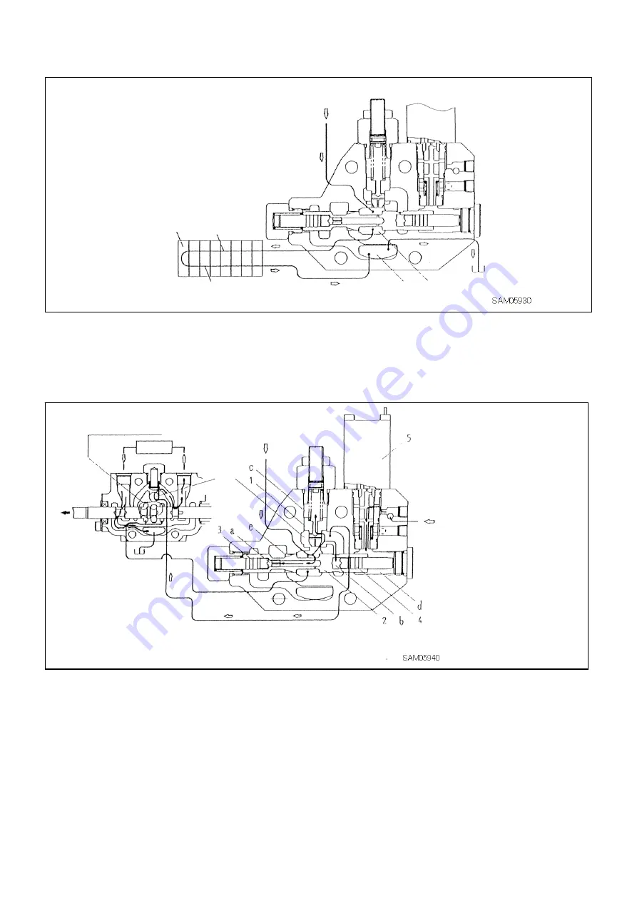
1. When each switching valve is in its neutral position
When each switching valve is in its neutral position, the hydraulic oil supplied from pump passes through the
central bypass path and tank path including this control valve, and returns to the tank through the discharge port
of the supply section.
2. When a switching valve is operated
(when the solenoid of negative magnetic proportional reducing
valve is not excited)
When any of the switching valves is switched, the central bypass path is closed, and the hydraulic oil pushes
detecting valve (1) upward to flow the oil into the parallel path. In this stage, pump pressure is applied to the
primary side chamber (a) of flow control spool (2), while load pressure (downstream pressure of the detecting
valve) is applied to the secondary side chamber (b) and the detecting valve spring chamber (c). Note that since
the primary side piston (3) and secondary side piston (4) have the same diameter, the front and rear differential
pressure of detecting valve (1) is applied to the rightward of the flow control spool (2).
On the other hand, the secondary pressure of negative magnetic proportional reducing valve (5) is applied to the
control valve’s spring chamber (d), and works in the leftward direction on the flow control spool (2) by overcoming
the spring force.
When the negative magnetic proportional reducing valve solenoid (SOL10) is not excited, the secondary
pressure reaches its maximum value, and the leftward force overcomes the rightward force acting on flow control
spool (2), and thus the flow control spool (2) is positioned at the extreme left end. Consequently, the control
notch (e) remains closed, and thus the hydraulic oil from pump totally passes the parallel path and flows into the
switching valve.
SOL10
Actuator
From pump
U turn cover
Central bypass path of
each switching valve
U turn cover
Tank path of each
switching valve
Tank path
Tank
Central bypass path
Parallel path
Central bypass path shut off
1. Detecting valve
2. Flow control spool
3. Primary side piston A
4. Secondary side piston B
5. Negative magnetic proportional reducing valve
Summary of Contents for MK0003
Page 2: ......
Page 8: ...0 6...
Page 12: ...1 4 2 DIMENSIONAL DRAWING OF OUTRIGGER WIDTH...
Page 17: ...1 9 4 WORKING RADIUS LIFTING HEIGHT...
Page 18: ...1 10 Working range diagram Outrigger extended to maximum Main boom 1 section...
Page 19: ...1 11 Working range diagram Outrigger extended to maximum Main boom 2 sections...
Page 20: ...1 12 Working range diagram Outrigger extended to maximum Main boom 2 5 sections...
Page 21: ...1 13 Working range diagram Outrigger extended to maximum Main boom 3 sections...
Page 22: ...1 14 Working range diagram Outrigger extended to minimum Main boom 1 section...
Page 23: ...1 15 Working range diagram Outrigger extended to minimum Main boom 2 sections...
Page 24: ...1 16 Working range diagram Outrigger extended to minimum Main boom 2 5 sections...
Page 25: ...1 17 Working range diagram Outrigger extended to minimum Main boom 3 sections...
Page 26: ...1 18 5 RATED TOTAL LOAD CHART...
Page 32: ...2 4...
Page 33: ...2 5 1 HYDRAULIC CIRCUIT DIAGRAM 200 1176600...
Page 34: ...2 6...
Page 35: ...2 7 2 HYDRAULIC PIPING DIAGRAM 2 1 CRANE ROTATING PART 200 1171800...
Page 41: ...2 13 2 2 CONTROL LINE A...
Page 43: ...2 15 2 3CONTROL LINE B Perform spiral winding on the entire perimeter of the hose of this part...
Page 45: ...2 17 2 4 TRAVEL LINE...
Page 47: ...2 19 2 5 OUTRIGGER LINE...
Page 49: ...2 21 2 6 PT LINE 102 1152000 4...
Page 69: ...2 41...
Page 70: ...2 42...
Page 71: ...2 43...
Page 76: ...2 48 4 8 ENGINE ACCESSORIES 102 1149200...
Page 90: ...2 62 7 2 INTERNAL STRUCTURE...
Page 120: ...2 92 Part B Writing method for wire number Two places...
Page 123: ...2 95 Figure 1 Index point Figure 2 Connection diagram...
Page 166: ...2 138 15 4 APPEARANCE OF OUTRIGGER ON REAR LEFT SIDE 200 2167300...
Page 173: ...2 145 17 ELECTRIC CIRCUIT DIAGRAM 200 1176500 01...
Page 174: ...2 146 18 ELECTRIC SYSTEM 18 1 1 WIRE HARNESS OF MACHINE BODY 1 200 1172200 1...
Page 176: ...2 148 18 1 2 WIRE HARNESS OF MACHINE BODY 2 200 1172200 2...
Page 179: ...2 151 19 CONTROL ASSEMBLY 19 1 CONTROLLER 1 TTC60 Pin arrangement...
Page 180: ...2 152 TTC60 I O...
Page 181: ...2 153 2 TTC36X Pin arrangement...
Page 182: ...2 154 TTC36X lower part I O...
Page 209: ...2 181 19 2 5 LIST OF CONTROLLER INPUT MONITORING...
Page 210: ...2 182 19 2 6 LIST OF CONTROLLER ANALOG INPUT OUTPUT MONITORING...
Page 245: ...3 9 1 2 3 ANGLE METER 360 S200M3297000...
Page 274: ...3 38...
Page 293: ...4 19 8 SERVICE LOCATIONS...
Page 294: ...4 20...
Page 296: ...5 2 1 ELECTRICAL MOTOR UNIT ASSEMBLY Unit weight 180 kg...
Page 324: ...5 30...
Page 325: ...5 31 4 ELECTRICAL DIAGRAM S200M3122000 01...
Page 326: ...5 32 S200M3122000 02...
Page 336: ...6 8 1 3 2 INTERNAL STRUCTURE OF WINCH MOTOR...
Page 345: ...6 17 4 WORKING RADIUS LIFTING HEIGHT OF ONE FALL WINCH...
Page 348: ......