


2-74
8.4 ACTIONS OF EACH SECTION
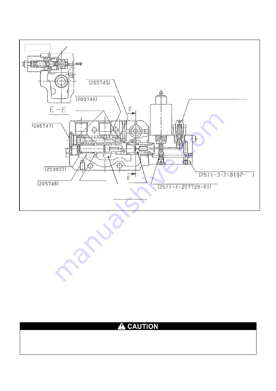
[1] Composition and actions of supply section
The supply section consists of a supply port (P) for supplying hydraulic oil from pump, oil channel to bring it to
operation section (switching section), and the discharge port (T) to discharge the return oil from actuator to tank; and
in addition, a back pressure valve (sequence valve), reducing valve, and relief valve.
The sequence valve is provided to secure the minimum operating pressure of pilot when magnetical switching under
no load and the reducing valve serves to maintain the pilot pressure at a specified value.
Since the sequence valve, reducing valve and relief valve are not working while no oil is allowed to flow, the paths of
pump to tank and pump to central bypass are closed, although the path from pump to the primary side of reducing
valve is allowed to flow.
When supplied from pump, the oil pushes the sequence valve to open and flows in the central bypass path. When the
switching valve in the downstream is not operated, the pump pressure at supply port (P) serves as the pressure of the
sequence valve.
(Cracking pressure: 1.34 to 1.49 MPa)
Concurrently, the reducing valve starts to maintain the pilot pressure at the set pressure of the reducing valve.
(Reducing valve set pressure: 1.42 to 1.47 MPa)
When the downstream switching valve is being operated, the pump pressure works as its load pressure, and as soon
as the negative pressure reaches the relief valve set pressure, the relief valve operates to maintain the circuit
pressure at the relief valve set pressure.
Also, when the emergency solenoid (SOL.9) is not excited, the circuit pressure can be set to the level of unloaded
state.
・
Limit the set pressure of relief valve within the range not exceeding the rated pressure of the valve.
Using it at a pressure exceeding the rated pressure may invite a performance drop, failure or breakage.
各パイロット
制御ラインへ
T
T
P
T
一次側(
P)
非常停止
(SOL
9
)
二次側
減圧弁
(
背圧弁
)
リリーフ弁
センターバイパス通路
Reducing valve
Primary side (P)
Relief valve
Set value: 20.6 MPa (210 k)
Filter receptacle
Each pilot on the secondary side
To the control line
Filter (10
μ
m)
O-ring 1BP7
(
2 spots)
Filter plug
Spring guide
Sequence valve spring
Sequence valve
(Back pressure
valve)
Emergency stop
Unloading section - Assembly
Pilot spool (normally open)
Supplying section -
Assembly
Central bypass path
Summary of Contents for MK0003
Page 2: ......
Page 8: ...0 6...
Page 12: ...1 4 2 DIMENSIONAL DRAWING OF OUTRIGGER WIDTH...
Page 17: ...1 9 4 WORKING RADIUS LIFTING HEIGHT...
Page 18: ...1 10 Working range diagram Outrigger extended to maximum Main boom 1 section...
Page 19: ...1 11 Working range diagram Outrigger extended to maximum Main boom 2 sections...
Page 20: ...1 12 Working range diagram Outrigger extended to maximum Main boom 2 5 sections...
Page 21: ...1 13 Working range diagram Outrigger extended to maximum Main boom 3 sections...
Page 22: ...1 14 Working range diagram Outrigger extended to minimum Main boom 1 section...
Page 23: ...1 15 Working range diagram Outrigger extended to minimum Main boom 2 sections...
Page 24: ...1 16 Working range diagram Outrigger extended to minimum Main boom 2 5 sections...
Page 25: ...1 17 Working range diagram Outrigger extended to minimum Main boom 3 sections...
Page 26: ...1 18 5 RATED TOTAL LOAD CHART...
Page 32: ...2 4...
Page 33: ...2 5 1 HYDRAULIC CIRCUIT DIAGRAM 200 1176600...
Page 34: ...2 6...
Page 35: ...2 7 2 HYDRAULIC PIPING DIAGRAM 2 1 CRANE ROTATING PART 200 1171800...
Page 41: ...2 13 2 2 CONTROL LINE A...
Page 43: ...2 15 2 3CONTROL LINE B Perform spiral winding on the entire perimeter of the hose of this part...
Page 45: ...2 17 2 4 TRAVEL LINE...
Page 47: ...2 19 2 5 OUTRIGGER LINE...
Page 49: ...2 21 2 6 PT LINE 102 1152000 4...
Page 69: ...2 41...
Page 70: ...2 42...
Page 71: ...2 43...
Page 76: ...2 48 4 8 ENGINE ACCESSORIES 102 1149200...
Page 90: ...2 62 7 2 INTERNAL STRUCTURE...
Page 120: ...2 92 Part B Writing method for wire number Two places...
Page 123: ...2 95 Figure 1 Index point Figure 2 Connection diagram...
Page 166: ...2 138 15 4 APPEARANCE OF OUTRIGGER ON REAR LEFT SIDE 200 2167300...
Page 173: ...2 145 17 ELECTRIC CIRCUIT DIAGRAM 200 1176500 01...
Page 174: ...2 146 18 ELECTRIC SYSTEM 18 1 1 WIRE HARNESS OF MACHINE BODY 1 200 1172200 1...
Page 176: ...2 148 18 1 2 WIRE HARNESS OF MACHINE BODY 2 200 1172200 2...
Page 179: ...2 151 19 CONTROL ASSEMBLY 19 1 CONTROLLER 1 TTC60 Pin arrangement...
Page 180: ...2 152 TTC60 I O...
Page 181: ...2 153 2 TTC36X Pin arrangement...
Page 182: ...2 154 TTC36X lower part I O...
Page 209: ...2 181 19 2 5 LIST OF CONTROLLER INPUT MONITORING...
Page 210: ...2 182 19 2 6 LIST OF CONTROLLER ANALOG INPUT OUTPUT MONITORING...
Page 245: ...3 9 1 2 3 ANGLE METER 360 S200M3297000...
Page 274: ...3 38...
Page 293: ...4 19 8 SERVICE LOCATIONS...
Page 294: ...4 20...
Page 296: ...5 2 1 ELECTRICAL MOTOR UNIT ASSEMBLY Unit weight 180 kg...
Page 324: ...5 30...
Page 325: ...5 31 4 ELECTRICAL DIAGRAM S200M3122000 01...
Page 326: ...5 32 S200M3122000 02...
Page 336: ...6 8 1 3 2 INTERNAL STRUCTURE OF WINCH MOTOR...
Page 345: ...6 17 4 WORKING RADIUS LIFTING HEIGHT OF ONE FALL WINCH...
Page 348: ......