Maeda MK0003 Service Manual Download Page 172

2-144 

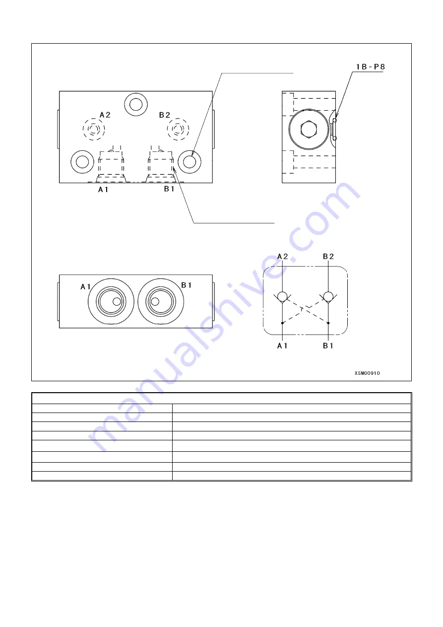
16.3 DOUBLE PILOT CHECK VALVE 


Specifications 

Rated pressure 

20.6 MPa (210 kgf/cm

2

Test pressure 

41.2 MPa (420 kgf/cm

2

Max. flow rate 

10L/min 

Allowable leak amount 

0.05 L/min (pressurizing 17.2 MPa [175 kgf/cm

2

] from A2 and B2 ports)

Check cracking pressure 

0.49 MPa (5 kgf/cm

2

Pilot area ratio 

6.2:1 

Test oil temperature range 

50 ± 5°C 

Operating temperature range 

10 to +80°C 


3-6.5 through 
12 counter sinking, depth 6 


2 - G1/4 (JIS O-ring type) 

Circuit diagram 

Summary of Contents for MK0003

Page 1: ...this service manual are the references for the services such as disassembling and assembling Be sure to ALWAYS refer to the latest parts catalog the latest information before ordering any part since t...

Page 2: ......

Page 3: ...CRANE ROTATING PART 2 7 2 1 1 HOSE GUIDE 2 8 2 2 CONTROL LINE A 2 13 2 3 CONTROL LINE B 2 15 2 4 TRAVEL LINE 2 17 2 5 OUTRIGGER LINE 2 19 2 6 PT LINE 2 21 2 7 ELECTRO HYDRAULIC PIPING ON MACHINE BODY...

Page 4: ...ECTION 2 74 8 5 FAILURE CAUSE AND COUNTERMEASURE 2 81 9 OUTRIGGER SELECT VALVE 2 82 9 1 APPEARANCE AND SPECIFICATIONS 2 82 9 2 INTERNAL STRUCTURE 2 84 9 3 INSPECTION OF VALVES 2 85 9 4 METHODS FOR OPE...

Page 5: ...RIC CIRCUIT DIAGRAM 2 145 18 ELECTRIC SYSTEM 2 146 18 1 1 WIRE HARNESS OF MACHINE BODY 1 2 146 18 1 2 WIRE HARNESS OF MACHINE BODY 2 2 148 18 2 CONTROL UNIT ASSEMBLY 2 149 19 CONTROL ASSEMBLY 2 151 19...

Page 6: ...4 2 1 2 WORKING OF SETTING DETECTION 3 25 2 2 OR STOWAGE DETECTION 3 26 2 2 1 OR STOWAGE DETECTION ASSEMBLY 3 26 2 2 2 WORKING OF OR STOWAGE DETECTION DEVICE 3 27 2 3 OR POSITION DETECTION 3 28 2 3 1...

Page 7: ...TAL OPERATOR 5 9 2 4 DETAIL OF INVERTER SET ITEMS 5 10 2 5 ALARM DISPLAY AND COUNTERMEASURE 5 13 2 6 LIST OF ALARM CODES 5 15 2 7 TROUBLESHOOTING 5 19 2 8 MAINTENANCE AND INSPECTION 5 25 2 9 NOTE ABOU...

Page 8: ...0 6...

Page 9: ...ENSIONAL DRAWING OF OUTRIGGER WIDTH 1 4 3 PRINCIPLE SPECIFICATION LIST 1 5 4 WORKING RADIUS LIFTING HEIGHT 1 9 5 RATED TOTAL LOAD CHART 1 18 6 CRANE STANDARD PRESSURE AND OPERATING TIME TABLE 1 19 7 P...

Page 10: ...1 2 1 OUTSIDE DRAWING 1 1 STANDARD SPECIFICATIONS Standard specifications Standard specifications with winch attached...

Page 11: ...1 3 1 2 ENGINE AND ELECTRIC MOTOR SPECIFICATIONS Electric Motor Specifications Electric Motor Specifications with winch attached...

Page 12: ...1 4 2 DIMENSIONAL DRAWING OF OUTRIGGER WIDTH...

Page 13: ...0 mm Boom length 3rd section 6030 mm Boom extending speed 3 44 m 15 5 sec Derricking system Derricking type Hydraulic double acting cylinder direct acting type 2 Boom derricking angle time 0 to 80 36...

Page 14: ...output continuous 7 4 kW 2500 min 1 10 1 PS 2500 rpm Fuel tank capacity 12 L Battery Model 55B24R Safety device Over hoist detector and stop system over un winding detector overload preventive device...

Page 15: ...ec Derricking system Derricking type Hydraulic double acting cylinder direct acting type 2 Boom derrick angle time 0 to 80 36 0 sec main boom 1st stage jib 1st stage Jib Telescoping system Jib type Te...

Page 16: ...ifications Three phase induction motor 5 5 kW 4P 380 V 50 Hz Starting method Inverter controlled 30 Hz to 60 Hz Safety device Over hoist detector and stop system over un winding detector overload prev...

Page 17: ...1 9 4 WORKING RADIUS LIFTING HEIGHT...

Page 18: ...1 10 Working range diagram Outrigger extended to maximum Main boom 1 section...

Page 19: ...1 11 Working range diagram Outrigger extended to maximum Main boom 2 sections...

Page 20: ...1 12 Working range diagram Outrigger extended to maximum Main boom 2 5 sections...

Page 21: ...1 13 Working range diagram Outrigger extended to maximum Main boom 3 sections...

Page 22: ...1 14 Working range diagram Outrigger extended to minimum Main boom 1 section...

Page 23: ...1 15 Working range diagram Outrigger extended to minimum Main boom 2 sections...

Page 24: ...1 16 Working range diagram Outrigger extended to minimum Main boom 2 5 sections...

Page 25: ...1 17 Working range diagram Outrigger extended to minimum Main boom 3 sections...

Page 26: ...1 18 5 RATED TOTAL LOAD CHART...

Page 27: ...ricking 0 to 80 Hoist up 12 3 1 36 3 Hoist down 13 7 1 51 4 Jib derricking 0 to 90 Hoist up 4 9 1 26 3 Hoist down 6 0 1 40 4 Raising 1 fall 1m 5th layer main 2 stages 50 jib 2 stages 50 after run up o...

Page 28: ...9 2 Jib derricking cylinder 11 1 Main telescoping cylinder 11 2 Jib telescoping cylinder 1 Hydraulic oil tank 14 Solenoid valve 12 Slewing motor 2 Engine 3 Pump 8 OR select valve 7 Crane control valve...

Page 29: ...2 36 4 4 2 DIESEL FUEL STANDARDS 2 37 4 4 3 BIODIESEL FUEL 2 37 4 4 4 FUEL FEED TO FUEL SYSTEM 2 38 4 5 MAINTENANCE AND INSPECTION 2 39 4 6 TROUBLE SHOOTING 2 40 4 7 FUEL PIPING 2 44 4 7 1 FUEL LINE 2...

Page 30: ...TELESCOPIC CYLINDER 2 106 13 2 1 JIB NO 1 TELESCOPIC CYLINDER 2 108 13 2 2 JIB NO 2 TELESCOPIC CYLINDER 2 110 13 3 JIB TELESCOPIC CYLINDER HYDRAULIC SCHEMATIC DIAGRAM 2 112 13 4 COUNTER BALANCE VALVE...

Page 31: ...ING AND REASSEMBLING BOOM 2 184 20 1 REMOVING WIRE HARNESS CONNECTORS 2 184 20 2 REMOVING HYDRAULIC HOSES 2 185 20 3 PREPARING HOISTING ACCESSORIES 2 186 20 4 REMOVING THE ROD PIN AND FOOT PIN OF MAIN...

Page 32: ...2 4...

Page 33: ...2 5 1 HYDRAULIC CIRCUIT DIAGRAM 200 1176600...

Page 34: ...2 6...

Page 35: ...2 7 2 HYDRAULIC PIPING DIAGRAM 2 1 CRANE ROTATING PART 200 1171800...

Page 36: ...IDE No 1 hose guide Extension 1 EX1 No 2 hose guide Sandwich the hose to fix Extension 2 EX2 No 3 hose guide Sub extension 2 STA2 Sub contraction 2 STB2 Sub raising 2 SDA2 Sub lowering 2 SDB2 Sandwich...

Page 37: ...ions No Item number specifications C4 59 22031 45500 1068 06PF 20 MDA 22779S83085 NN173 04 850L spiral on entire perimeter 1005 1005 11 22611 11130 1071 04 A Main D cylinder Main raising 8 22611 11135...

Page 38: ...1005 Jib contraction Connection Table for Cableveyor Action Piping Hose Piping Joint Port Connection destination Action No Item number specifications No Label Item number specifications No Item numbe...

Page 39: ...al on entire perimeter label MTA 23 MTB hose main contraction 1 NN173 04 1000L 1005 1005 spiral on entire perimeter label MTB 24 SDA1 hose sub raising 1 1 NN173 04 2500L 1005 1005 spiral on entire per...

Page 40: ...Cableveyor 2 Item number S200B3173000 48 Sems bolt 16 Komatsu item number 01024 80612 49 Sems bolt 12 Komatsu item number 01024 80620 50 Hose adapter 2 1067 06 51 Hose adapter 1 1009 04 52 Slow retur...

Page 41: ...2 13 2 2 CONTROL LINE A...

Page 42: ...047708 6 22511 07350 A4 PLT 4 22511 07230 2 353 4438000 2 5 22511 35210 PP Number Name Q ty Note 1 Main select pipe 1 Item number 350 2047700 1 1 Main select pipe D1 1 Item number 350 2047701 1 2 Main...

Page 43: ...2 15 2 3CONTROL LINE B Perform spiral winding on the entire perimeter of the hose of this part...

Page 44: ...6 B Left Number Name Q ty Note TA hose extended 1 NN173 04 2160L 1005 0590 spiral on entire perimeter label TA 2 TB hose contracted 1 NN173 04 1800L 1005 0590 spiral on entire perimeter label TB 3 WA...

Page 45: ...2 17 2 4 TRAVEL LINE...

Page 46: ...1 1 Item number 353 3202100 2 2 Travel pipe R2 1 Item number 353 3202200 2 3 Travel pipe L1 1 Item number 353 3202300 2 4 Travel pipe L2 1 Item number 353 3202400 2 5 Flareless type joint 6 LLM UR 10...

Page 47: ...2 19 2 5 OUTRIGGER LINE...

Page 48: ...2611 11030 B In 13 22031 43300 A12 9 22611 11030 3 OR3 22779SF3245 1 OR1 22779SF3110 9 22611 11030 A OR4 Out B12 9 22611 11030 3 OR3 22779SF3245 1 OR1 22779SF3110 9 22611 11030 B In Number Name Q ty N...

Page 49: ...2 21 2 6 PT LINE 102 1152000 4...

Page 50: ...e port bracket Connection Table for Tank T Line Equipment name Port Joint Hydraulic hose Joint Port Connection destination No Item number No Mark Item number No Item number Manifold block Part No 6 D1...

Page 51: ...3 Hose adapter 1 1034 06 24 Hose adapter 1 1009 04 25 Hexagon head bolt 2 M8 1 25 16L plated 26 Plain washer 2 M8 Regular circle plated 27 Spring washer 6 M8 Type 2 plated 28 Manifold block 1 1 Item n...

Page 52: ...re perimeter label WDr 59 Dr hose 1 NWP35 9 700L 1005 0590 spiral on entire perimeter label Dr 60 SDr hose 1 PA0306 C C 1900L spiral on entire perimeter label SDr 61 T1 hose 1 NWP35 12 2100L 1005 ML90...

Page 53: ...2 25 2 7 ELECTRO HYDRAULIC PIPING ON MACHINE BODY SIDE 32 67 200 2167400 PT line 32 Suction PT line 67 Adjust the hanging ring of the coupler cap so that it does not come off...

Page 54: ...the PT line assembly Number Name Q ty Note 1 Adapter bracket 1 Item number 200 4640200 2 Sems bolt 2 Komatsu item number 01024 81020 3 Flat face coupler male 1 Item number 25580 01200 F35 6P Nitto 4...

Page 55: ...number S101J2063000 2 9 OIL COOLER P T Dr LINE Item number 353S60700000 From winch drain Blanki To hydraulic oil tank 2 G1 4 O ring port From crane control valve Drawn cup 4 0 2P Black paint Louverle...

Page 56: ...r item number 1114 2 3 Compression spring 1 Manufacturer item number 1114 3 4 Missing number 5 Stopper 1 Manufacturer item number 1114 4 6 Snap ring 1 Manufacturer item number No 50014 Specifications...

Page 57: ...ing torque Target 6 Nm Range 5 2 6 9 Nm Caution Be careful not to allow dust to enter the tank Apply to both sides of hatched area SAM05690 Instruction drawing for applying liquid packing to members A...

Page 58: ...20L plated 9 Spring washer 4 M5 Type 2 plated 10 Plain washer 4 M5 Regular circle plated 11 Packing RF 1 Item number 329 4286900 1 12 Liquid packing ThreeBond 1207B 13 Hydraulic oil 25L VG32 grade 14...

Page 59: ...umber 353 4451000 2 Connector 1 Item number 353 4450700 3 Plate 1 Item number 350 4408400 4 Housing 1 Item number 350 4410900 5 Spring 2 Item number 350 4408800 6 O ring 2 P 14 Type 1 A 7 Steel ball 2...

Page 60: ...older 1 6 Valve assembly 1 7 Set screw 1 M5 12 Specifications Oil used Hydraulic oil ISO VG32 46 Flow rate 25L min Max 40L min Oil temperature 20 C to 120 C Filtration accuracy 30 as per JIS B 8356 no...

Page 61: ...tation direction Left rotation viewed from the flywheel side Lubricating oil used Engine oil SD or higher class SAE30 when cold SAE20 Dry mass 84 0 5 kg Fuel system Fuel used JIS K2204 No 2 light oil...

Page 62: ...2 34 4 2 ENGINE APPEARANCE 4 200 1175000 Filter wrench Note Bend the oil level gauge with reference to the above dimensions Detail of level gauge Fuel filter wrench...

Page 63: ...mber 121468 44520 1 11 Three way cock 1 Item number 129150 49100 1 12 Air cleaner 1 Item number 119440 12520 1 13 Intake pipe 1 Item number 119631 12650 1 14 Silencer 1 Item number 119325 13500 1 15 G...

Page 64: ...tamination of lubricating oil occurs and cylinder liners and piston rings are worn out prematurely 3 Blockage or corrosion of nozzle hole of fuel injection valve Imperfect combustion causes wear corro...

Page 65: ...the recommended value is less than 0 1 The aromatic content must be less than 35 of the total volume However the recommended value is less than 30 PAH polynuclear aromatic hydrocarbon must be less tha...

Page 66: ...When biodiesel fuel which does not conform to the standards specified by a diesel engine manufacturer and diesel fuel injection equipment manufacturer is used or deteriorated biodiesel fuel as descri...

Page 67: ...ust valve heads Lapping of intake and exhaust valve seats Electrical equipment Inspection of warning lamps Inspection of battery fluid amount and auxiliary charge Lubricating oil Inspection of engine...

Page 68: ...2 40 4 6 TRUOBLE SHOOTING The table below summarizes general symptoms and causes If an abnormal symptom appears take measures before it develops into a big accident...

Page 69: ...2 41...

Page 70: ...2 42...

Page 71: ...2 43...

Page 72: ...9 Nm Normally the above is already adjusted at the time of delivery Before adjustment After adjustment Fo filter Fuel pump Fuel schematic diagram Fuel tank Pre filter Blue Yellow connection power supp...

Page 73: ...ama fuel hose nominal size 8 410L 8 Fuel hose 2 1 Yokohama fuel hose nominal size 8 60L 9 Fuel hose 3 1 Yokohama fuel hose nominal size 8 300L 10 Fuel hose 4 1 Yokohama fuel hose nominal size 8 190L 1...

Page 74: ...Item number 4700 68000 0 3 Strainer 1 Item number 4700 69000 0 4 Cap 1 Item number 353 4452100 5 Packing 1 Item number 353 4438700 6 Cross recessed round head screw 5 M4 x 0 7 x 10L 7 Spring washer 5...

Page 75: ...L SENDER Number Name Q ty 1 Mounting plate 1 2 Tongue wire 1 3 Housing 1 4 Cover 1 5 Tube 1 6 Float NBR 1 7 Terminal 2 8 Upper insulator 1 Performance Float position FULL EMPTY Value of resistance Ohm...

Page 76: ...2 48 4 8 ENGINE ACCESSORIES 102 1149200...

Page 77: ...ated 29 Hexagon head bolt 1 21015M08070 M8 x 1 25 x 70L plated 30 Hexagon head bolt 4 21015M10016 M10 x 1 5 x 16L plated 31 Hexagon head bolt 10 21015M10025 M10 x 1 5 x 25L plated 32 Hexagon head bolt...

Page 78: ...ashiki Kako QKA020 56 Bracket for engine sling 1 102 4599900 57 Rubber cushion seat 1 102 4602300 58 Boss 2 102 4602500 59 Hexagon head bolt 2 21015M08075 M8 x 1 25 x 75 plated 60 Plain washer 1 21741...

Page 79: ...5100 3 Hexagon head bolt 8 M10 1 5 25L Strength grade 8 8 plated 4 Hexagon socket head cap screw 2 M12 1 75 30L Strength grade 12 9 5 Spring washer 8 M10 Type 2 plated 6 Conical spring washer 2 M12 2H...

Page 80: ...esh Maximum 2600 min 1 Line filter 10 m Variable control mechanism Fixed horsepower control Vibration level Within 10G Direction of rotation Right seen from the spindle side Suction pressure 0 02 to 0...

Page 81: ...Snap ring 1 58 Missing number 11 Needle 3 35 Snap ring 1 59 Missing number 12 Rocking pin 2 36 Snap ring 1 60 Seal ring with hexagon socket 1 13 Packing 1 37 Missing number 61 Hexagon nut 1 14 Spring...

Page 82: ...figure a single port each for the intake and discharge is provided this system comprises a pair of intake port and discharge port each on the outside P1 and the inside P2 Every other pump box in row o...

Page 83: ...load F1 from the piston side is located in the direction indicated in the figure below and generates a rotational moment in the clockwise direction as looked at the swash plate Against this setup a sp...

Page 84: ...he coupling Repair or replace the pump Abnormal noise or vibration occurs Cavitation phenomenon Air or water inclusion in the hydraulic oil Suction piping is clogged or squeezed Piston shoe swaging is...

Page 85: ...r port B backward G3 8 Specifications Maximum flow rate on board P1 P2 15 L min CO 30 L min Internal leakage at 9 8 MPa 50 to 55 C Each spool 200 mL min maximum Main relief valve both P1 and P2 20 6 0...

Page 86: ...lder 4 18 Inlet housing 1 31 O ring 1A P12 4 6 Compression spring 2 19 Plug 2 32 O ring 1B P9 2 7 Seal holder 4 20 Plunger housing 2 33 O ring 1B P10 2 8 Backup ring 4 21 Open spool 2 34 O ring 1B P12...

Page 87: ...rosion deformation or breakage of spring holder and cover Replacement Spool sealing area Outward oil leakage Stain corrosion or deformation of seal holder Repair or replace Repair or replace Main reli...

Page 88: ...replacement but the overhaul of the circuit may be required Check the spool diameter and determine if it should be replaced Check the spool for its straightness and other characteristics and repair or...

Page 89: ...ed Equivalent to ISO VG 32 46 Reduction gear ratio 1 36 96 Oil temperature 20 C to 100 C Hydraulic motor Capacity 9 7 cm 3 rev Filtering 10 m Maximum service pressure 20 6 MPa 210 kgf cm 2 Gear oil SA...

Page 90: ...2 62 7 2 INTERNAL STRUCTURE...

Page 91: ...IPLES Stationary section Parking brake Carrier 2 Rotating section Counter balance valve Hydraulic motor Simplified planetary gear reducer 2 stages Note b 1 associates 4 planetary gears while b 2 assoc...

Page 92: ...pled or integrated with the shaft with gear S2 and the rotation of gear S2 is single stage reduced between gears S2 b2 and a2 The single stage reduced revolution is double stage reduced between the sp...

Page 93: ...with hydraulic oil the oil flows in the cylinder port in the cylinder barrel 4 corresponding to the port A and thrusts piston 6 This thrusting force is converted to a rotary force by means of swash p...

Page 94: ...draulic oil is supplied through port B the motion of the above mentioned parts will be in the reverse direction and thus the hydraulic runs in reverse Subsequently as the hydraulic oil in port A is sh...

Page 95: ...he pinched position between the steel plates 6 and 7 that are likewise fixed to body 2 5 Resultantly the rotation of cylinder barrel 3 is stopped by the friction force between disk plate 4 and steel p...

Page 96: ...ion of rotation 2 Piping port is covered at the time of delivery When piping be careful not to let dust from welding scale to go inside 3 Since this is an inside drain type product drain pressure pres...

Page 97: ...emove the plug of the filler port 3 2 Refill the lubricating oil up to LEVEL 3 3 Close the plug of the filler port Note When removing both plugs at the LEVEL side and DRAIN side of the filler port rem...

Page 98: ...ent of each unit Malfunction of hydraulic motor Drop of volume efficiency caused by abnormal abrasion due to catching foreign matters Replacement of broken parts kit Does not stop or delays to stop Ma...

Page 99: ...8 B1 Derrick cylinder bottom up G3 8 B3 Telescopic cylinder head retracted G3 8 A2 Winch motor port B lower G3 8 A4 Slewing motor port B left G3 8 B2 Winch motor port A upper G3 8 B4 Slewing motor por...

Page 100: ...10 and 11 1 7 A for flow rate control valve and accelerator positioner controlling Conducting rating Continuous Continuous power ON causes the solenoid to be heated to a high temperature May cause a...

Page 101: ...tion the operation begins with the actuator under the lowest load pressure Additionally this valve has a central bypass path for releasing under no load the oil supplied from the pump while the switch...

Page 102: ...t supply port P serves as the pressure of the sequence valve Cracking pressure 1 34 to 1 49 MPa Concurrently the reducing valve starts to maintain the pilot pressure at the set pressure of the reducin...

Page 103: ...diameter the front and rear differential pressure of detecting valve 1 is applied to the rightward of the flow control spool 2 On the other hand the secondary pressure of negative magnetic proportion...

Page 104: ...trol notch e to close As a result the hydraulic oil pushes detecting valve 1 to open so that it can flow into the parallel path to drive the actuator Further decreasing the applied current allows the...

Page 105: ...SOL11 of magnetic proportional reducing valve 4 allows the reducing valve spool 1 to be pushed down by push pin 5 for an amount corresponding to the current value to control the secondary pressure in...

Page 106: ...at can move spool 1 is generated Further since spool 1 employs the all port block type in the neutral spool position between parallel path c actuator paths d1 and d2 as well as between actuator paths...

Page 107: ...ath d1 on the right side are connected together and concurrently actuator path d2 and tank path f are connected together and thus the actuators begin to move When the solenoid on the left is excited a...

Page 108: ...Reducing valve spool 1 moves until reducing valve spring 2 comes to be balanced and squeezes the path a of reducing valve spool 1 to maintain the secondary pressure at the set value 3 When secondary p...

Page 109: ...with a diluent Spool sliding is not smooth Spool catches foreign matters Loss of oil film between the spool and body due to an abnormal oil temperature rise Spool is unevenly abraded Failure in lubri...

Page 110: ...OR1 in B3 OR1 in A5 Contraction A4 Contraction OR2 out A6 OR2 out B5 Extension B4 Extension OR2 in B6 OR2 in A8 Up A7 Right OR3 out A9 OR3 out B8 Down B7 Down OR3 in B9 OR3 in A11 Raising A10 Raising...

Page 111: ...gf cm 2 DR port allowable back pressure 7 MPa 71 4 kgf cm 2 Mass Approx 7 5 kg Material Aluminum Allowable range of votage variation Rated voltage 10 Solenoid type D SOL 019 with bullet terminals Rate...

Page 112: ...2 84 9 2 INTERNAL STRUCTURE Solenoid block D S01 019 1 set 6 port switching valve D HD 01081 4 units Pilot switching valve D HD 01068 1 unit...

Page 113: ...the spool 21 for any abrasion or other types of damage Replace the valve Wash and reassemble Check the pilot pressure 1 to 1 5 MPa Raise the pilot pressure Pilot switching valve Disassemble and inspec...

Page 114: ...y resulting in malfunctioning Limit the tightening torque of a mounting bolt within a range of 6 to 8 N m 2 When tightening a mounting bolt pay attention to prevent the O ring from being squeezed out...

Page 115: ...ch is located to the side of the monitor case It is placed side by side to the emergency canceling switch The action of each lever while operation is being changed to outrigger operation is as follows...

Page 116: ...the running lever side Apply Loctite 262 Derrick raised DA Telescopic cylinder head retracted TB Winch drain WDR Winch upper WB Winch lowered WA Telescopic boom extended TA Telescopic cylinder head r...

Page 117: ...hose Telescopic cylinder bottom port extended G3 8 TA TA hose OR select valve B5 port G3 8 TB T hose Telescopic cylinder head port retracted G3 8 TB TB hose OR select valve A5 port G3 8 DA DA hose Der...

Page 118: ...sing number 4 17 Hexagon socket head cap plug R1 8 14 4 Flange 1 11 Missing number 4 18 Missing number 5 Missing number 12 Missing number 6 19 Shaft assembly 1 6 Missing number 13 Rivet screw 2 4 8 2...

Page 119: ...se side Height 2 Wire number mentioned Mounting hole of 8 5 5 On a 173 circumference Draining hole of 6 5 5 On a 130 circumference Top Bottom Note 1 The diameter of the wire on the rotor side should b...

Page 120: ...2 92 Part B Writing method for wire number Two places...

Page 121: ...crew 000540209 2 M4 20 29 Clamp seat VA25364 1 30 Hexagon socket head cap bolt 001950101 2 M5 10 31 Spring washer 003840009 9 M4 32 Shrinkable tube 4 W3 F2 3 8 33 Electric wire AEX 0 5 mm2 2 See note...

Page 122: ...ations Common to CUP 1 and 2 Effective electrical angle 350 1 2 Total resistance rate 5 kOhms 15 Linearity 0 1 Electrical Rating 1W 70 C 3 Water resistance 4 Power output Refer to figure 3 8 Index poi...

Page 123: ...2 95 Figure 1 Index point Figure 2 Connection diagram...

Page 124: ...e number Color Type 1 Red Twisted pair electric wire 0 5 mm 2 2 Blue 3 Green AEX 0 5 mm 2 4 Red AESSX 2 0 mm 2 5 Black A Red AEX 0 5 mm 2 B Black C Blue D White E Yellow F Brown Notes 1 Twisted pair e...

Page 125: ...promptly 1 Check to ensure that the hook can be turned smoothly If it fails to turn smoothly replace it 2 If any abrasion crack or damage is found on the hook replace it promptly 3 Check the shackle...

Page 126: ...ght and left sides of the boom surface equally Detail of undersurface slide plate Screw in until it hits at the time of full contraction of the boom and make adjustments by returning it by one and a h...

Page 127: ...on nut 4 M12 1 75 Type 1 plated 4T 24 Extending sheave B3 2 Item number 315 3080801 25 Extending sheave pin B3 2 Item number 315 4111001 26 Stopper B3 2 Item number 315 4111100 27 Collar B3 2 Item num...

Page 128: ...737 0225 000 figure number 4674739 55 Hexagon head bolt 12 M6 1 0 12L plated 4 6 56 Spring washer 12 M6 type 2 plated 57 Seal ring with hexagon socket 2 M10 1 5 50L flat point 58 Hexagon nut 2 M10 1...

Page 129: ...12 2 JIB 200 1171500 Boom length 1822 4057 No 3 Sub boom 1578 No 2 Sub boom 1709 No 1 Sub boom 1700 Adjust shims so that the side plate firmly contacts the right and left sides of the boom surface eq...

Page 130: ...4627200 18 Hexagon head bolt 32 M8 1 25 20L plated 10 9 19 Spring washer 32 M8 Type 2 plated 20 Side plate 8 Item number 315 4176301 21 Side stopper plate 8 Item number 315 4176200 22 SSP shim Proper...

Page 131: ...0900 5 End plate 1 Item number 350 4394000 6 Sems bolt 4 Komatsu item number 01024 81235 7 Sems bolt 2 Komatsu item number 01024 80816 8 Lynch pin 1 Item number 21570 08045 9 Ring 4 Item number 315 41...

Page 132: ...marking Detail drawing P Tightening torque 88 2 98 N m M30 x 1 5 Tightening torque 29 4 N m R1 4 Tightening torque 13 7 N m R1 8 Hydraulic circuit diagram Tightening torque 7 6 N m M6 x 1 0 Applicati...

Page 133: ...K1 Main cylinder seal kit 1 Main telescopic cylinder specifications Cylinder bore x Rod bore Stroke 65 x 45 1720st Specification value Normal load When extended 58 2 kN at 20 6 MPa 5 8t at 210 kgf cm...

Page 134: ...octite 263 or equivalent Tightening torque 117 6 N m M16 x 2 0 Application of Loctite 263 or equivalent Mask the plug part It is not acceptable to paint the inlet part Detail drawing V It is acceptabl...

Page 135: ...copic cylinder specifications Cylinder bore x Rod bore x Stroke 55 40 1105st Specification value Normal load When extended 48 9 kN at 20 6 MPa 4 9t at 210 kgf cm 2 When contracted 23 1 kN at 20 6 MPa...

Page 136: ...equivalent Tightening torque 7 6 N m M6 x 1 0 Application of Loctite 222 or equivalent Caulk at two locations after tightening Tightening torque 13 7 N m R1 8 Tightening torque 63 7 N m M10 x 1 5 Tigh...

Page 137: ...ng K2 1 1B P24 13 Backup ring K2 2 T3 P24 14 O ring K2 2 1B P16 15 Backup ring K2 2 T2 P16 16 Bushing 1 Oiles Corporation LFB 1610 17 Dog 1 18 Set screw 1 Cup point M6 6 19 Pipe 1 20 Stopper 1 21 Plug...

Page 138: ...TELESCOPIC CYLINDER S200F3083001 Tightening torque 7 6 N m M16 x 1 0 Application of Loctite 222 or equivalent Caulk at two locations after tightening Tightening torque 784 6 N m M39 x 2 0 Tightening...

Page 139: ...40 50 6 7 Dust seal K3 1 Kayaba 7 wiper 40 50 6 8 8 O ring K3 1 1B P50A 9 Jib No 2 cylinder piston 1 10 Wear ring K3 1 Sakagami Seisakusho WPB 55A 11 Piston packing K3 2 Sakagami Seisakusho RGY 55 12...

Page 140: ...EMATIC DIAGRAM A B C D E F 3 No 2 telescopic cylinder No 3 boom for extension and contraction Sequence valve Mechanical check valve No 1 telescopic cylinder No 2 boom for extension and contraction A e...

Page 141: ...y The telescopic cylinder and derrick cylinder contract during work Boom lowers Failure of check seat part 1 or 2 or biting of foreign matter Damage to O ring 1 or 2 3 and 4 The pilot hole 0 3 is clog...

Page 142: ...2 114 13 4 3 WORKING DIAGRAM 1 When neutral 2 When extending 3 When contracting When neutral Load When extending Pressure oil Return oil Return oil Pressure oil When contracting Load Load...

Page 143: ...essure 0 245 MPa 2 5 kgf cm 2 Operating force 0 65 x pressure 20 kg Operating temperature range 10 to 90 C Tightening torque during valve assembly 0 98 to 0 18 MPa 10 to 12 kgf m 13 5 2 WORKING DIAGRA...

Page 144: ...m B port Check cracking pressure 0 196 MPa 2 kgf cm 2 Pilot pressure 1 18 0 3 MPa 12 3 kgf cm 2 with the valve open Operating force 0 5 x pressure 3 kg Operating temperature range 10 to 80 C Cracking...

Page 145: ...2 117 13 7 MAIN DERRICK CYLINDER ASSEMBLY 200 1171900 E Bottom side G3 8 F Rod side G3 8 B Rod side G1 4 A Bottom side G1 4...

Page 146: ...ber 200 4629200 4 Lowering pipe 1 Item number 200 4629300 5 D joint plate 1 Item number 200 4629400 6 Gall N 1 Item number 329 4275700 7 Hexagon head bolt 2 M10 1 5 50L plated 4 8 8 Spring washer 2 M1...

Page 147: ...anufacture marking Tightening torque 9 8 N m 1 0 kgf m Tightening torque 470 7 N m 48 kgf m M44 x 2 0 Hydraulic schematic diagram M10 x 1 5 Screw depth 15 Detail of port part Scale 1 1 two locations C...

Page 148: ...3000 1B P41 15 Set screw 1 359S70914000 Cup point M6 12 K1 Repair kit common to right and left 1 359S70915000 Specifications Cylinder bore x Rod bore Stroke 70 45 655st Normal load When extended 79 3...

Page 149: ...rque 29 4 N m G1 4 2 M8 x 1 25 Screw depth 16 Tightening torque 470 7 N m M44 x 2 0 M10 x 1 5 Screw depth 15 Tightening torque 7 6 N m M6 x 1 0 Application of Loctite 222 or equivalent Caulk at two lo...

Page 150: ...00F3285170 R1 8 18 Orifice 1 S200F3285180 S0805 19 Plug 2 S200F3285190 GPF1 4 20 O ring K1 2 S200F3285200 1B P11 21 Cap 1 Cap for protecting paint 80 Plug 4 1 4 Resin plug 81 Plug 2 3 8 Resin plug K1...

Page 151: ...Name Q ty Note 1 Jib D cylinder 1 Item number S200F3084000 2 Jib D cylinder rod cover 1 Item number 200 3345700 3 Sems bolt 1 Komatsu item number 01024 81220 4 Rod guide cover 2 Item number 101 457020...

Page 152: ...ue 882 6 N m M33 x 2 0 M12 x 1 75 Screw depth 20 Manufacture marking Hydraulic circuit diagram Pressure sensor Pressure sensor Tightening torque 7 8 N m R1 16 Tightening torque 13 7 N m R1 8 Tightenin...

Page 153: ...4 S200F3084200 YS item number 01008 00008 21 Body valve 1 S200F3084210 YS item number 910 74 03670 22 O ring K1 2 S200F3084220 YS item number 05001 11424 23 Hexagon socket head cap screw 2 S200F308423...

Page 154: ...ISO VG32 Tightening torque 235 4 264 9 N m 24 27 kg m Use a torque wrench Apply Loctite 262 Tightening torque 78 5 N m 8 kg m Use a torque wrench Apply Loctite 262 Tightening torque 235 4 264 9 N m 2...

Page 155: ...M12 Type 3 16 Grease nipple SN MK0049 1 Item number 24711 2000 C R1 8 Lubricating oil 0 6 ISO VG320 standard item After assembling the slewing reduction gears and hydraulic motor feed lubricating oil...

Page 156: ...315S07313000 14 Square head plug R1 2 2 315S07314000 15 Hexagon socket head cap screw M6 18L 6 315S07315000 16 Spring washer M6 6 315S07316000 17 Snap ring S 50 1 315S07317000 When removing the reduc...

Page 157: ...96 cc rev Rated speed 560 min 1 Maximum speed 670 min 1 Rated torque 147 N m 15 kgf m Maximum torque 206 N m 21 kgf m Rated pressure 12 3 MPa 125 kgf cm 2 Maximum pressure 16 7 MPa 170 kgf cm 2 Allowa...

Page 158: ...380 80008 0 8 Thrust bearing race 1 4380 80009 0 9 Shaft output 1 4380 80011 0 10 Housing 1 4380 80012 0 11 Ball check valve assembly 1 4380 80013 0 12 Thrust needle bearing 1 4380 80014 0 13 Screw 4...

Page 159: ...n the tank completely come out Cavitation of pump and motor If the motor is rotated at a load of large motor inertia negative pressure is generated and cavitation is caused resulting in breakage Mixin...

Page 160: ...e adjustments with respect to a state in which OR cylinder is at stroke end Adjust so that there is no looseness when OR is stowed Gap 0 0 5 mm Secure gap between the top of 11 OR and 28 stay damper I...

Page 161: ...2 350 4394000 19 Hexagon head bolt M8 10 2 21015M08010 20 Hexagon head bolt M8 16 2 21015M08016 21 Hexagon head bolt M8 20 4 21017M08020 22 Hexagon head bolt M8 25 2 21017M08025 23 Sems bolt 4 Komats...

Page 162: ...justment amount Make adjustments with respect to a state in which OR cylinder is at stroke end Adjust so that there is no looseness when OR is stowed Gap 0 0 5 mm Install so that the surface does not...

Page 163: ...Hexagon head bolt M8 16 2 21015M08016 21 Hexagon head bolt M8 20 4 21017M08020 22 Hexagon head bolt M8 25 2 21017M08025 23 Sems bolt 4 Komatsu item number 01024 81225 24 Spring washer M8 10 21711M0800...

Page 164: ...tamp of M at end face Pay attention during assembly Secure gap between the top of 11 OR and 28 stay damper 40 Guideline of adjustment amount Make adjustments with respect to a state in which OR cylind...

Page 165: ...Hexagon head bolt M8 16 2 21015M08016 21 Hexagon head bolt M8 20 4 21017M08020 22 Hexagon head bolt M8 25 2 21017M08025 23 Sems bolt 4 Komatsu item number 01024 81225 24 Spring washer M8 10 21711M080...

Page 166: ...2 138 15 4 APPEARANCE OF OUTRIGGER ON REAR LEFT SIDE 200 2167300...

Page 167: ...2 350 4394000 19 Hexagon head bolt M8 10 2 21015M08010 20 Hexagon head bolt M8 16 2 21015M08016 21 Hexagon head bolt M8 20 4 21017M08020 22 Hexagon head bolt M8 25 2 21017M08025 23 Sems bolt 4 Komats...

Page 168: ...IONS 200 3353200 Install by turning it 90 sideways Adjust gap with shims B Rod side G1 4 Adjust gap with shims A Bottom side G1 4 Incline outward by 45 Adjust for each cylinder Rotary Apply lithium gr...

Page 169: ...D rod guide cover 2 347 4388600 Specifications Cylinder bore Rod bore Stroke 80 50 305st Normal load When extended 103 5 kN at 20 6 MPa 10 6t at 210 kgf cm 2 When contracted 63 1 kN at 20 6 MPa 6 4t...

Page 170: ...tions after tightening Tightening torque 7 6 N m Tightening torque 637 N m Tightening torque 4 N m Tightening torque 9 8 N m Y view Tightening torque 2 5 N m Hydraulic circuit Fixed restriction Contra...

Page 171: ...T3 P70 K1 1 05005 14070 11 O ring 1B G80 K1 1 05001 18031 12 Piston 1 930 32 80030 13 Piston ring SPGW 80 K1 1 05023 00080 14 Wear ring K1 1 06001 18020 15 O ring 1B P44 K1 1 05001 14435 16 Set screw...

Page 172: ...flow rate 10L min Allowable leak amount 0 05 L min pressurizing 17 2 MPa 175 kgf cm 2 from A2 and B2 ports Check cracking pressure 0 49 MPa 5 kgf cm 2 Pilot area ratio 6 2 1 Test oil temperature rang...

Page 173: ...2 145 17 ELECTRIC CIRCUIT DIAGRAM 200 1176500 01...

Page 174: ...2 146 18 ELECTRIC SYSTEM 18 1 1 WIRE HARNESS OF MACHINE BODY 1 200 1172200 1...

Page 175: ...s 43 1 Electrical equipment box 1 102 2138600 43 Engine electrical equipment box assembly 1 200 2164300 41 3 Relay bracket 1 102 4584600 41 2 Relay 3 349S55626000 41 1 Relay harness 1 200 3351900 41 R...

Page 176: ...2 148 18 1 2 WIRE HARNESS OF MACHINE BODY 2 200 1172200 2...

Page 177: ...re locking Back of the case Electronic key 1 1 2 of the transmitter must match the Serial No Serial No Install so that the connector comes to the front Serial No is on upper face of 4 and 5 Inside of...

Page 178: ...x 25L plated 15 Packing 2 2 200 4646300 14 Packing 1 2 200 4646200 13 Case lid 1 200 4637300 12 Sems bolt 2 01024 81025 Komatsu item number 11 Case 1 200 1168600 10 Sems bolt 4 01024 80670 Komatsu ite...

Page 179: ...2 151 19 CONTROL ASSEMBLY 19 1 CONTROLLER 1 TTC60 Pin arrangement...

Page 180: ...2 152 TTC60 I O...

Page 181: ...2 153 2 TTC36X Pin arrangement...

Page 182: ...2 154 TTC36X lower part I O...

Page 183: ...105 0 120 1 108 2 119 3 107 0 122 1 110 2 121 3 109 LS power supply Firm output 1 132 Extension contraction switching valve 1 Acceptable to checkoutput abnormality 2 143 Raising lowering switching val...

Page 184: ...ITOR SCREEN 1 Monitor 1 Travel mode screen When all of four outriggers are in a stowed state the travel mode screen is displayed When even one outrigger is cancelled from the stowed state the screen c...

Page 185: ...ger extension lamp MAX 2 3 No 2 Outrigger extension lamp MAX 2 4 No 2 Outrigger setting lamp 2 5 No 4 Outrigger setting lamp 2 6 No 4 Outrigger extension lamp MAX 2 7 Jib and main boom stowage lamp 2...

Page 186: ...igger individual operation screen of the monitor 3 1 4 Collective outrigger ON button Use this switch to operate the 4 outriggers simultaneously When Collective outrigger ON button is pressed the four...

Page 187: ...on Use this switch to display the service content When Service screen selector button is pressed the screen changes to the service screen of the monitor 5 1 9 Crane mode button Use this button to chan...

Page 188: ...turns on and indicates that the outriggers are set The lamp lights up in green when the outrigger tray sets and blinks in red when the tray floats stowed The conditions of the outrigger trays are dete...

Page 189: ...detected by the potentiometer on upper part of rotary joint 2 Detection of stowing in the main boom horizontal direction The lamp turns on in green when the main boom stops at the horizontal stowing...

Page 190: ...lewing Upon slewing of the main boom out of the four divided lamps the one in the slewing direction turns blue The main boom slewing position is detected by the potentiometer on upper part of rotary j...

Page 191: ...ns are enabled 3 4 Engine oil pressure abnormality display Indicates a drop in engine oil pressure It is normal if the monitor lights up when the main starter switch is turned ON and comes off as engi...

Page 192: ...enish fuel NOTES Fill the fuel tank to full at the end of work for the day Even if the starter switch is turned ON a regular remaining amount is not displayed for a while in some cases but this is not...

Page 193: ...pper right is pressed the screen returns to the home screen of the monitor 2 1 Home button 2 No 4 outrigger IN button 3 No 4 outrigger OUT button 4 No 3 outrigger IN button 5 No 3 outrigger OUT button...

Page 194: ...the outriggers can be stowed When you release your finger from the button the outrigger cylinders stop 3 5 8 and 10 outrigger OUT buttons Use these buttons to set up the outriggers When the Outrigger...

Page 195: ...ration can be performed Even if the condition is set to the fixed hook specification select Winch with the winch installation selector button of 3 when the winch unit is installed on the boom When the...

Page 196: ...home button to return to the home screen of the monitor 2 3 Winch installation selector button Pressing the Winch installation selector button turns the blue circle on the left to green and the moment...

Page 197: ...en returns to the home screen of the monitor 2 1 Cursor move button 2 Cursor move button 3 Set OK button 4 Page change button 5 Micro speed 3 setting button 6 Micro speed 3 reset button 7 Display sett...

Page 198: ...o speed 3 setting button When this button is pressed the Micro Speed 3 Setting screen is displayed Move the cursor or to the desired item to set and press the Set OK button The speed for that item can...

Page 199: ...oes not perform the reset Y Performs the reset Then press the Set OK button to determine the selection 7 Display setting screen button When this button is pressed the display changes to the Display Se...

Page 200: ...ss the Hour meter clock change button then move the cursor or to the desired item to set That item can be determined 7 2 Mute button By pressing this button the button tone can be set to the mute mode...

Page 201: ...tness can be adjusted and determined 7 4 Clock setting button By pressing this button the clock can be set Press the Clock setting button then move the cursor or to the desired item to set By pressing...

Page 202: ...f life of the replacement part and its expire time can be viewed and set Replace the part within the expire time by referring to Inspection and Maintenance After completion of replacement select the r...

Page 203: ...itching button is pressed again the screen returns to the user setting screen 1 Service mode button 2 Manufacturer mode button 1 Service mode button See 19 2 3 Service mode Password input screen The p...

Page 204: ...is displayed Crane related screen 2 2 When the page switching button is pressed the page is switched and the page of Data logger monitoring Error record Moment limiter calibration mode or Slew angle...

Page 205: ...tton or and press the Enter button N No zero adjustment is performed Y Zero adjustment is performed When Y is pressed zero adjustment of the levelling instrument is performed in a machine state when t...

Page 206: ...error was detected 1st Time when an error was detected Latest Time when an error was detected last Moment limiter calibration mode See Safety Device 1 6 moment limiter Calibration procedure for the ca...

Page 207: ...nge can be made Select using the cursor move button or and press the Enter button Slewing gain The setting of LO MID HI of slewing gain can be changed Select using the cursor move button or and press...

Page 208: ...t Mode MD L M H J1 T C Low position Middle position High position Jib single fall Traveling Caribration Outrigger 1 setting O1 SM SO OM OO Rotary STD Other Top Inner Max Other Outrigger 2 setting O2 S...

Page 209: ...2 181 19 2 5 LIST OF CONTROLLER INPUT MONITORING...

Page 210: ...2 182 19 2 6 LIST OF CONTROLLER ANALOG INPUT OUTPUT MONITORING...

Page 211: ...ROR 4 8V 5V 20sec continuous 32 STROKE SENSOR 1 4 POWER ERROR 4 8V 5V 20sec continuous 33 STROKE SENSOR 2 3 POWER ERROR 4 8V 5V 20sec continuous 34 BATTERY VOLTAGE ERROR 11 5V Engine state both runnin...

Page 212: ...e pair Make the nut side of the bracket back Route the harness along the innermost hose and piping Make the nut side front Yellow tape must not enter the drum Tighten clip together with gall Same for...

Page 213: ...EXTENSION 32 and JIB CONTRACTION 33 from the Jib telescoping cylinder 5 Disconnect the hydraulic hose from clip 38 Caution Apply a blanking plug to the disconnected hose coupling so that no dust will...

Page 214: ...RIES 1 Fix the main boom and jib to prevent the jib from dropping 2 Apply wires to the main boom in 2 fall hanging as shown in the figure Lift the load up at its center of gravity Boom hanging wire Ji...

Page 215: ...shioning object to the rod pin knock it with a hammer to pull it out Watch out for sudden falling of the main derricking cylinder 2 Take off the foot pin Apply a steel pipe or other cushioning object...

Page 216: ...ng object to each of the pins and knock it with a hammer to pull it out Pay attention to prevent losing the balance 3 Remove the two link pins B and the jib derricking cylinder head pin This completes...

Page 217: ...mer to pull it out 3 Loosen nuts 20 and 21 at the end of extending wire rope 19 and dismount them from boom No 1 4 Loosen nut 23 at the end of contracting wire rope 22 and dismount them from boom No 1...

Page 218: ...for trunnion pin 17 and pull it off by using a plier or the like 2 Dismount each of sieves 24 and 35 cover 31 slide plates 43 and 47 side stop plate 53 and hexagon socket set screw 57 3 From boom No...

Page 219: ...ull off the telescopic cylinder from the front end of boom No 3 2 Remove the contracting wire cover B 39 and unhook the contracting wire rope 22 from boom No 3 3 Unfold the two plates on boom No 3 and...

Page 220: ...G THE MAIN BOOM EXTENDING CONTRACTING WIRE ROPES 1 With the main boom in a horizontal position reciprocate the boom to extend and retract for two to three times 2 During the retracting operation check...

Page 221: ...ending wire rope 6 according to step 4 Adjustment of No 3 boom extending wire rope 2 3 Adjustment of No 3 boom retracting wire rope 1 1 With the lock nut 3 loose tighten the right and left adjusting n...

Page 222: ...telescopic cylinder coupling connector adapter and hose adapter 2 Take off the four upper and lower members of slide plate 16 as well as the side stop plate 21 and shim 22 3 From Jib No 1 pull off the...

Page 223: ...in the extracting bolt M8 X 30 L or thereabouts into the M8 tap hole for trunnion pin 7 and pull it off by using a plier or the like 2 Take off the four upper and lower members of slide plate 16 as w...

Page 224: ...step screw in the extracting bolt M8 X 30 L or thereabouts into the M8 tap hole for trunnion pin 8 and pull it off by using a plier or the like 2 Dismount the T guide rollers 11 3 Pull out the telesc...

Page 225: ...WITH OPTIONAL WINCH 1 For a machine equipped with an optional winch first unhook the winch wire and disconnect the hydraulic hose to the winch and then perform the disassembling operation of the boom...

Page 226: ...the wedge socket 2 Remove the wire clip and unhook the end of wire rope from the wedge socket 3 Take up the wire rope with the drum by winding up the winch In this operation apply a tension to the wi...

Page 227: ...hose coupling so that no dust will intrude and no leakage will occur Be aware that the swivel joint port name and hose label name are contrary to each other Fix to winch drum with optional winch assem...

Page 228: ...of top and inner boxes 4 units X approx 34 kg per unit totaling approx 136 kg Set the outrigger in the maximum extending position Leave the position pin remaining inserted Take off one of the split pi...

Page 229: ...connect the connectors OR top and inner Take off the clip for inner cable Take off the OR pin A stopper plate Remove the OR pin check bolt and while holding the OR top remove the OR pin A Take off the...

Page 230: ...er unit approx 180 kg 1 Install the outrigger and allow its footage to be suspended at 80 mm or thereabouts above ground 2 Stop the engine 3 Remove 4 fixing bolts 2 of the power unit cover 1 4 Remove...

Page 231: ...ve position is aligned with the ball position Check for their positions Attach a coupler cap to removed couplers respectively so that dust or water droplets are not adhered to the couplers 8 Remove co...

Page 232: ...overhead crane allow the hook to stand by right above the power unit CAUTION When lifting with the machine itself avoid allowing the jib to be below 90 while performing the operation It stops automat...

Page 233: ...sed without power unit being installed the counterweight must be mounted instead See 21 3 1 REMOVING THE COUNTERWEIGHT for how to mount the counterweight Perform mounting the power unit in the reverse...

Page 234: ...castor wheels are not mounted on the counterweight mount them The counterweight can be removed without castor wheels but transporting the counterweight is easier with castor wheels 3 Set hook to lifti...

Page 235: ...ract jib for lifting up and extend jib for lifting down To lift by winch system raise hook for lifting up and lower hook for lowering down NOTES Slowly operate to make sure travelling levers do not hi...

Page 236: ...utomatically 3 After lifting up the counterweight slowly lower it down to hooking section of the frame falling prevention from straight above and lock the hooking section To lift by fixed hook retract...

Page 237: ...ECTION 3 25 2 2 OR STOWAGE DETECTION 3 26 2 2 1 OR STOWAGE DETECTION ASSEMBLY 3 26 2 2 2 WORKING OF OR STOWAGE DETECTION DEVICE 3 27 2 3 OR POSITION DETECTION 3 28 2 3 1 OR POSITION DETECTION ASSEMBLY...

Page 238: ...y stop cancel switch 3 Controller 2 pieces at the bottom of monitor 1 piece inside post 4 Total length of main boom side of main boom 5 Total length of jib side of jib 6 Main boom angle meter side of...

Page 239: ...rushed Lower surface of hose guide Fix the lock nut by restricting the length total reel tip so that it does not come off Yellow tape must not enter the drum Fix the lock nut by restricting the length...

Page 240: ...5500 27 Sems bolt 2 Komatsu item number 01024 81020 28 Connector plate 2 Item number 200 4655700 29 Cord guide 2 Item number 200 4655600 30 Plain washer 8 M10 Regular circle plated 31 Hexagon nut 4 M1...

Page 241: ...1 TOTAL LENGTH REEL Note When replacing the total length reel do not allow the yellow tape of the main cord to enter the drum If the main cord enters the drum the potentiometer will malfunction S200M...

Page 242: ...Sub cord assembly 1 25 Microphone cord assembly 1 26 Note label 1 27 Special washer 1 28 Hexagon cap nut 4 M4 29 Iron small sized sems screw 2 M4 x 8 with plain washer and spring washer 30 Iron small...

Page 243: ...Vinyl electric wire for equipment PVC 3 x 0 5 mm 2 Outside diameter 6 7 Affixation position of name plate Potting agent Silicone resin based Connector barb fitting electronics amplifier Econoseal J S...

Page 244: ...CP 2F Effective electrical angle 340 2 3 Total resistance value 1 kOhm 20 Index point Adjust the output in this illustration 0 to 15 3 Insulation resistance 200 MOhm or more DC 500V Withstand voltage...

Page 245: ...3 9 1 2 3 ANGLE METER 360 S200M3297000...

Page 246: ...nt 10mA MAX Temperature drift 1 08 MAX 0 3 FSMAX FS 360 at 30 to 80 C standard difference of 25 C Step response time constant Approx 0 3 seconds 25 C at inclination angle of 45 Oil viscosity 500 mm 2...

Page 247: ...oil temperature sensor 25 2 Item number S200J3315000 2 Pressure sensor cover 1 Item number 349 3204200 3 Hexagon head bolt with washer 2 M8 x 1 25 x 15L plated with PW and SW 200 3362700 Pressure sens...

Page 248: ...3 8A JIS B2351 Type 0 2 Medium contact part 17 4 PH Stainless Steel 3 Connector connection shape Deutsch DT04 4P 4 Protection structure IP67 5 Recommended tightening torque 70 to 75 N m 6 Terminal arr...

Page 249: ...0 000 cycles after application of FS pressure Temperature characteristics 0 15 FS 10 C Temperature output range 40 to 125 C Temperature compensation range 40 to 105 C Operating temperature range 40 to...

Page 250: ...er harness of the lower part To LS HR of controller harness of the lower part To LS TE of controller harness of the lower part To LS SR of controller harness of the lower part To LS HL of controller h...

Page 251: ...ight display 6 Rated total load display 2 Abnormality occurrence display 7 Working radius display 3 Display of number of jib sections 8 Display of number of main boom sections 4 Jib angle display 9 Ma...

Page 252: ...the calibration screen the safety devices are in the following state Slewing restriction Valid Grounding detection Valid Boom upper limit and lower limit switch Invalid Buzzer sounds Over hoisting se...

Page 253: ...dle position Before calibrating make sure actual position of fixed hook is also in Middle position When having calibrated Length be sure to calibrate Load When having calibrated Angle be sure to calib...

Page 254: ...cted to the minimum Use the cursor move button or so that the numerical value of SET is 2 59 0 m of TARGET and press the Enter button 1 1 1 2 Calibration of jib length Calibrate the boom length Select...

Page 255: ...imum Install an angle meter to the boom and set the boom angle to full raising Use the cursor move button or so that the numerical value of SET is 0 of the displayed value of the angle meter and press...

Page 256: ...al value of SET is the displayed absolute value 180 and press the Enter button Example When a displayed value is 1 40 1 40 180 178 60 This is a SET value When a displayed value is 1 55 1 55 180 178 45...

Page 257: ...op sway of the load and press the Enter button after 10 seconds Example Weight 800 kg Slinging wire 5 kg Hook 2 kg Set the value of SET to a total of 807 kg Be careful not to overwind when working wit...

Page 258: ...by pressing Slewing Angle Calibration Switch while pressing Emergency Canceling Switch Pressing only the Slewing Angle Calibration Switch does not switch the screen to Calibration Mode Going into the...

Page 259: ...the match mark in the post part to align the boom to the storage position If the boom has passed the storage position slew the boom again starting at around 20 degrees 1 2 Counterclockwise calibration...

Page 260: ...or cover 1 200 3356600 4 Pin 1 200 4635600 5 Sems bolt 4 Komatsu item number 01024 80616 6 Hexagon head bolt 2 M5 0 8 12L plated 4 8 7 Spring washer 2 M5 Type 2 plated 8 Plain washer 2 M5 Regular circ...

Page 261: ...the outrigger tray sets and blinks in red when the tray floats stowed If there is an abnormality in which the lamp 3 of the monitor does not light up when the outriggers are set inspect and repair th...

Page 262: ...rtion The number is for one side portion Joint tightening on the bracket Outrigger sensor harness CN RETRACT Wire harness assembly of machine body There must not be detection error due to looseness at...

Page 263: ...n head bolt 8 M4 0 7 x 25L plated 10 Spring washer 8 M4 Type 2 plated 11 Plain washer 8 M4 Small circle plated 2 2 2 WORKING OF OR STOWAGE DETECTION DEVICE The stowage state of outriggers is detected...

Page 264: ...lt 8 M6 1 0 v 14L plated 4 8 6 Hexagon head bolt 8 M8 1 25 16L plated 4 8 7 Spring washer 8 M4 Type 2 8 Spring washer 8 M6 Type 2 9 Spring washer 8 M8 Type 2 10 Plain washer 8 M4 Small circle plated 1...

Page 265: ...standard and besides the hole position 4 of the top box is set to MAX and the inner box 5 is pulled out to the maximum the outriggers are set to the maximum position and the lamp 2 of the monitor lig...

Page 266: ...x 16L plated 4 8 4 Spring washer 16 M6 Type 2 plated 5 Connector cover A 4 Item number 101 4587300 6 Hexagon head bolt 8 M6 1 0 45L plated 4 8 102 2145300 Note 1 Adjust the proximity switch by puttin...

Page 267: ...andard and besides the hole position 4 of the top box is set to MAX and the inner box 5 is pulled out to the maximum the outriggers are set to the maximum position and the lamp 2 of the monitor lights...

Page 268: ...ch 4 Item number 353S75813000 3 Hexagon head bolt with washer 8 M6 1 0 16L 4 Hexagon socket head screw 8 M6 1 0 16L 5 Spring washer 8 M6 Type 2 102 2145400 OR base OR top Inner box Detail drawing of p...

Page 269: ...boom is out of the storage position the lamp is turned off When the slewing angle of the boom is within the storage positon the lamp blinks green The lamp illuminates in green when all work equipments...

Page 270: ...34 2 6 SLEWING DIRECTION DETECTION 2 6 1 SLEWING DIRECTION DETECTION ASSEMBLY Number Name Q ty Note 1 Rotary brush 1 Item number S106L3569000 For details of the rotary brush refer to 10 3 ROTARY BRUS...

Page 271: ...ded lamps the one in the slewing direction turns blue The slewing position of the main boom is detected by the potentiometer above the rotary joint NOTES When the main boom is in the stowing direction...

Page 272: ...ss recessed pan head screw with washer 2 M4 0 7 20L with PW and SW plated 3 Buzzer assembly 1 Item number 200 4640800 4 Bolt with washer 1 M8 1 25 16L with PW and SW plated 200 3354000 Wire harness as...

Page 273: ...lination angle at the time of detection start 0 1 or less Operating temperature range 20 C to 70 C Storage temperature range 25 C to 75 C Withstand voltage AC 500V 1 minute between terminal batch and...

Page 274: ...3 38...

Page 275: ...NTS OF THE RECEIVER 4 8 2 2 INSPECTION AFTER TURNING ON THE TRANSMITTER 4 10 2 3 INSPECTION OF RECEIVER 4 10 3 SAFETY DEVICE OF REMOTE CONTROLLER 4 11 4 HANDLING BATTERY 4 12 4 1 REPLACEMENT TIMING OF...

Page 276: ...ping collective outrigger operation lever S4 Jib derricking S5 Jib telescoping No 2 outrigger operation lever S6 Slewing No 1 outrigger operation lever 1 2 LOWER PART COMPONENTS OF THE TRANSMITTER D1...

Page 277: ...the light emission pattern 2 ELECTRONIC KEY K1 The key has ID data necessary for operation of the Transmitter Install it on the Transmitter The remote controller does not operate unless serial No of t...

Page 278: ...eration dial engine speed to any position The maximum engine speed can be set to increase on the side 2 Set the speed selector rotary switch S10 to STD 3 When each operation lever is pushed down the C...

Page 279: ...ing normal operation 2 Error state 2 1 When the battery voltage is low Green Red Warning sound 0 5 seconds The battery replacement is required although operation is being performed 2 2 The initializat...

Page 280: ...en Red Warning sound 0 5 seconds Operation is disabled Replace the battery 2 4 Although the transmitter is normal there is no idle frequency of the high frequency module The battery voltage is normal...

Page 281: ...Green Red Warning sound 0 5 seconds Operation is disabled Either perform the operation manually by stopping the remote controller or turn the power ON again after a while 2 7 Configuration data error...

Page 282: ...4 8 2 COMPONENTS OF THE RECEIVER 2 1 COMPONENTS OF THE RECEIVER 1 Receiver 2 Monitor LED 3 Connector 4 Antenna 5 Monitor 6 Remote control mode display 7 Serial No...

Page 283: ...1 RECEIVER 1 The receiver receiving devices and control devices are stowed 2 MONITOR LED 2 The Transmitter cover is equipped with monitor LED that shows the operation status of the remote control sys...

Page 284: ...sh The failure of the remote control system is conceivable in the case of no entry when the second button input is performed for 10 seconds or longer NOTES The crane does not start to operate when the...

Page 285: ...ress the start button twice to turn the power ON 2 Electronic Key This system is provided with an electronic key The key has ID data necessary for the Transmitter and the system is not activated witho...

Page 286: ...r stops in a few minutes 4 2 REPLACEMENT METHOD OF BATTERY Replace the battery of the Transmitter in the procedure described below 1 Press the emergency stop switch S12 to turn the power of the transm...

Page 287: ...and charged 3 to 5 times Charge the battery at ambient temperature of 0 40C Charge the battery when the status LED D1 flashes in red and an intermittent signal sound starts to sound To avoid overdisch...

Page 288: ...k item Cause and Action Does the crane operate with the operation on the machine body side If the crane operates there is an abnormality in this equipment If the crane does not operate troubleshoot th...

Page 289: ...tion and press the start button twice Inspection repair replacement The emergency stop switch remains ON Cancel the emergency stop switch The battery is faulty the life of the battery etc Replace the...

Page 290: ...peration on the crane body side The outrigger crane selector switch is in the neutral N position Switch the outrigger crane selector switch The start button is pressed only once Press the start button...

Page 291: ...nd together with the fixing nut of the horn switch Insert into the back of horn CONTROL UNIT ASSEMBLY C To remote control receiver To inclination sensor CONTROL ASSEMBLY Tighten together with the case...

Page 292: ...mote control Electronic key unique address Automatic power OFF device Auto power off device Approx 15 minutes Transmitter stop function when battery capacity decreases Alarm switch Power of transmitte...

Page 293: ...4 19 8 SERVICE LOCATIONS...

Page 294: ...4 20...

Page 295: ...ANEL 5 8 2 2 EXTERNAL APPEARANCE AND NAME OF EACH SECTION 5 9 2 3 NAME AND CONTENT OF THE DIGITAL OPERATOR 5 10 2 4 DETAIL OF INVERTER SET ITEMS 5 12 2 5 ALARM DISPLAY AND COUNTERMEASURE 5 13 2 6 LIST...

Page 296: ...5 2 1 ELECTRICAL MOTOR UNIT ASSEMBLY Unit weight 180 kg...

Page 297: ...rew 3 M3 0 5 20L plated 23 Hexagon nut 3 M3 0 5 Type 1 plated 4T 24 Plain washer 3 M3 Small circle plated 25 Spring washer 3 M3 Type 2 plated 26 Plastic bit lock 1 Item number 353S69400000 CP 316 A Ta...

Page 298: ...w 1 Item number 22031 27500 2086 06 55 O ring boss female connector 1 Item number 22031 43500 1068 06 56 Male 45 elbow 2 Item number 22611 10650 1036 06 57 Coupler socket 2 Item number 25580 10600 F35...

Page 299: ...5 5 1 1 POWER UNIT 1 Power unit cover 2 Electric motor 3 Coupling 4 Hydraulic pump Power supply box...

Page 300: ...ariable control mechanism Fixed horsepower control Vibration level Within 10 G Direction of rotation Right seen from the spindle side Suction pressure 0 02 to 0 04 MPa Mass 13 kg Suction speed within...

Page 301: ...ther with the right hand front leg fixing bolt Adjust the direction of the harness connector route it through the long lacking part of the power unit BOX BKT and connect Comes out of the hole on the f...

Page 302: ...01024 80816 2 1 INVERTER PANEL 1 Power unit cover 2 Protective cover 3 Inverter panel 4 DC12V Power supply switch 5 Alternating current circuit power supply switch 6 Power lamp white 7 Trouble lamp re...

Page 303: ...5 9 2 2 EXTERNAL APPEARANCE AND NAME OF EACH SECTION 3G3MX2 A4055 V1 1 Cooling fan cover 2 Cooling fan 3 Cooling fin 4 Main unit case 5 Terminal block cover 6 Option cover 7 Electric wire drawer panel...

Page 304: ...the deceleration after the run command OFF Monitor LED Hz Lights up in green when the data displayed in the display part is frequency Monitor LED A Lights up in green when the data displayed in the d...

Page 305: ...put mode confirms the blinking line and moves the blinking line to the right Increment key Adds parameter or setting data Accelerates if long pressed Enters the individual input mode where each line c...

Page 306: ...081 Selection of first AVR 01 Normally OFF A082 Selection of first motor receiving voltage 400 Default value setting not necessary b001 Selection of restart during momentary power interruption and und...

Page 307: ...current and past alarms can be observed in the fault monitor 1 to 6 d081 to d086 The latest alarm is displayed in the fault monitor 1 d081 Precautions The inverter status at the time of alarm may be d...

Page 308: ...gital operator The trip status can be reset if 00 enable or 02 enable only reset is set for the stop key selection b087 Enter reset input from the control circuit terminal block Set 18 RS reset in one...

Page 309: ...ct Adjust so that it is correct Overload protection of the limiting resistor Trips when the activity ratio of the regenerative braking exceeds the activity ratio configured in b090 E06 Are there any s...

Page 310: ...being turned ON If residual voltage exists in the motor this function will not operate E14 Are there any ground faults Check the output line and motor Are there any faults in the inverter itself Remo...

Page 311: ...eration Check the brake Is the b124 setting short Make the b124 long Is the brake check signal being inputted Check the wirings Emergency cutoff 3 Trips when the safety input of GS1 or GS2 has been in...

Page 312: ...he encoder is below the start frequency b082 continues consecutively for more than the encoder breakage detection time P077 0 when the output frequency is above the creep speed setting P015 E80 Breaka...

Page 313: ...tput frequency setting monitor F001 if the primary frequency command selection A001 is 02 operator Input the frequency according to the setting value of the primary frequency command selection A001 th...

Page 314: ...urn OFF the corresponding terminal 84 ROK run OK signal is assigned to the multi function input terminal and it is in OFF state Turn ON the assigned terminal There is a breakage in the wiring from the...

Page 315: ...motor The 3 wire input function is used and the non inversed rotation inversed rotation logic is incorrect Check the 22 F R 3 wire non inversed inversed logic of the multi function input terminal The...

Page 316: ...tion overcurrent restriction function selection b130 enabled The value in the deceleration overcurrent restriction ratio gain b133 deceleration overcurrent restriction reset time b134 is inappropriate...

Page 317: ...on is being used check that the setting is correct and fix accordingly The circuit breaker activates when running the inverter The leakage current of the inverter is large Reduce the carrier frequency...

Page 318: ...g function selection P200 to 00 standard Modbus address Overload protection E05 occurs on brake control Inverter is running in brake restrain state Release the run command of the inverter in brake res...

Page 319: ...rion Check item Cycle Inspection method 1 Room environment 1 Dust temperature gas As required 1 Visual inspection thermometer olfaction 1 Improve areas of concern 2 Dripping of water and other liquid...

Page 320: ...used in the inverter tends to decay if left for a long period without any electricity flowing If not being used for a long period allow electricity to flow for at least five hours once in two years s...

Page 321: ...ng with the print board shall be replaced General Criterion for the Inspection Items Whether there is any liquid leakage Whether the safety valve is open Measurements of electric capacity and measurem...

Page 322: ...ts are Industrial Waste Collectors and Transporters or Industrial Waste Disposal Operators If the industrial waste is collected transported and disposed by non qualified personnel penalties may apply...

Page 323: ...5 29 3 POWER SUPPLY BOX 1 Power supply box 2 Power supply box door 3 Door handle 4 Terminal block 5 Cable inserting hole...

Page 324: ...5 30...

Page 325: ...5 31 4 ELECTRICAL DIAGRAM S200M3122000 01...

Page 326: ...5 32 S200M3122000 02...

Page 327: ...BOX HARNESS 200 3353900 Comes out of the hole on the frame The harness is built into the inverter board assembly If electrical unit only the parts are separately To the control panel assembly Electric...

Page 328: ...lt 2 Komatsu item number 01024 80816 3 Electric motor box accelerator harness 1 Item number 200 4644800 4 Electric motor box harness 1 Item number 200 3350900 5 Lamp blind connector 1 Item number 200...

Page 329: ...INCH MOTOR 6 8 1 3 3 FAILURE CAUSE AND COUNTERMEASURE 6 10 1 3 4 PRECAUTIONS IN WINCH MOTOR 6 10 1 4 OVER LOWERING DETECTION DEVICE 6 12 1 5 IRREGULAR WINDING PREVENTION ROLLER 6 12 2 OVER HOISTING PR...

Page 330: ...sheave 5 Wire rope 6 Sheave at upper part of main boom tip 7 Upper part of main boom tip Guide sheave 8 Intermediate upper part of main boom Guide sheave 9 Winch drum 10 Rope wedge 11 Weight for detec...

Page 331: ...separate package Fix to winch drum with optional winch assembly wedge WA hose A upper WDr hose WB hose Be careful that A and B ports of swivel joint and A and B ports of winch are upside down Winch lo...

Page 332: ...in 4 Item number 21561 10001 nominal size 10 JASO F 203 88 26 Sheave assembly 1 Item number 300S18400000 27 Sheave collar N 2 Item number 1832 16019 0 figure number 4673675 28 Snap sheave 1 Item numbe...

Page 333: ...it is not tightened Tightening torque Arrangement is different from 305C Three winding stop When winch cover is installed Tightening torque Tightening torque Apply Loctite 262 Apply Loctite 262 Apply...

Page 334: ...x Regular circle plated 22 Hexagon nut 4 M8 1 25 Type 1 plated 4T 23 Collar 7L 2 Item number 336 4331800 24 Roller spacer 4 Item number 103 4566900 25 Wedge 1 Item number 1835 16007 0 figure number 4...

Page 335: ...Torque 1030 N m 105 kgf m Max Output Revolution 123 min 1 Specifications of Hydraulic Oil Motor Capacity per Stroke 17 3 cm 3 rev Max Common Use Pressure 20 6 MPa 210 kgf cm 2 Max Revolution 3200 min...

Page 336: ...6 8 1 3 2 INTERNAL STRUCTURE OF WINCH MOTOR...

Page 337: ...122 Spool 1 125 Stopper 1 22 Taper Roller Bearing 4 199 Name Plate 1 126 Spring 2 23 Needle Bearing 4 102 Shaft 1 128 Orifice 2 5 Shaft 1 103 Thrust Plate 1 129 Plug 1 Spar Gear 1 104 Cylinder Block...

Page 338: ...t is normal there is often other cause C Normal torque cannot be achieved 6 Normal pressure is not generated due to an error in the circuit on the motor inlet side 7 Abnormally high pressure is genera...

Page 339: ...gear oil from the port or to the level of refuel port for refilling 6 Tighten plugs to ports Always use seal tapes when tighten plugs 3 Maintenance Perform daily maintenance and inspection of items be...

Page 340: ...2 INSPECTION OF EXCESSIVE UNWIND DETECTOR When the hook is lowered and 3 loops or less of wire rope is left in the winch drum check if the alarm sounds peep continuously and hook lowering action stop...

Page 341: ...hly Fix so that 10 moves smoothly Retighten using a pair of pliers to prevent from loosening Install a blind connector Insert into LS OH Reinstall 14 after removing it Insert into the blind cap Retigh...

Page 342: ...VER HOISTING PREVENTION DEVICE 1 OPERATION OF OVER HOIST PROTECTIVE DEVICE 11 Weight 12 Over hoist detector 13 Hook block When the hook block 13 approaches the tip of the jib and pushes up the weight...

Page 343: ...e conforms The wire rope is coiled Exercise caution not to form a kink in the rope when winding it up Be sure to unravel by rotating the rope to pull it out of the winch drum Use the following procedu...

Page 344: ...through the wedge socket 14 as shown in the diagram to the right 9 2 The rope wedge 10 should be in position a and yank at the wire rope 5 in the direction indicated by the arrow 10 Attach the wire c...

Page 345: ...6 17 4 WORKING RADIUS LIFTING HEIGHT OF ONE FALL WINCH...

Page 346: ...ius 9 73 m Maximum lifting height above ground 66 5 m Winch system Type Swash plate axial piston motor differential planetary gear type friction disc type brake Hook hoist speed 37 8m min drum5layers...

Page 347: ...umber 200E SM1608 02 First edition May 25 2015 Third edition Aug 8 2016 Issued by MAEDA SEISAKUSHO CO LTD 1095 Onbegawa Shinonoi Nagano City Nagano Prefecture 388 8522 Japan http www maesei co jp Any...

Page 348: ......

Reviews: