


2-38
[Precautions in using biofuel]
1. Free methanol in FAME can corrode FIE (fuel injection equipment) part made from aluminum and zinc.
2. Free water in FAME can cause clogging of the fuel filter and increase generation of bacteria.
3. Viscosity can become high when cold, which makes it hard for fuel to flow. Besides, an operation error of the fuel
injection pump or faulty atomization of the injection nozzle may be caused.
4. FAME may adversely affect a part of rubber materials (sealing parts, etc.). This causes fuel to leak, which causes
lubricating oil to be diluted.
5. Even when biodiesel fuel conforming to appropriate standards is used, attention needs to be paid to maintain fuel
quality in the equipment and fuel tank. It is important always to replenish clean and new fuel. It is sometimes
necessary to periodically wash away contamination of the fuel system and fuel storage vessel.
6. When biodiesel fuel, which does not conform to the standards specified by a diesel engine manufacturer and
diesel fuel injection equipment manufacturer, is used, or deteriorated biodiesel fuel as described in the above
precautions is used, this may not be covered by engine manufacturer's warranty.
4.4.4 FUEL FEED TO FUEL SYSTEM
In the following cases, it is necessary to feed fuel to the fuel system before starting the engine.
•
Before starting the engine for the first time
•
After fuel runs out and the fuel tank is replenished with fuel
•
After maintenance and inspection of the fuel system is performed
such as replacement of the fuel filter, drain of the oil/water separator
and replacement of fuel system parts
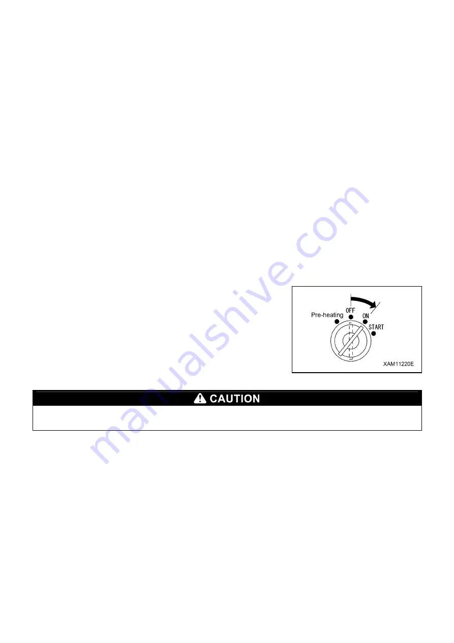
Feed fuel to the fuel system following the procedure below.
•
Turn the main starter switch of the vehicle to the ON position and
hold it for 10 - 15 seconds. This enables the solenoid feed pump to
feed fuel to the fuel system.
Never turn the starter switch to feed fuel to the fuel system. Otherwise, the starter may be heated, which may break
the coil, pinion gear, ring gear, etc.
Summary of Contents for MK0003
Page 2: ......
Page 8: ...0 6...
Page 12: ...1 4 2 DIMENSIONAL DRAWING OF OUTRIGGER WIDTH...
Page 17: ...1 9 4 WORKING RADIUS LIFTING HEIGHT...
Page 18: ...1 10 Working range diagram Outrigger extended to maximum Main boom 1 section...
Page 19: ...1 11 Working range diagram Outrigger extended to maximum Main boom 2 sections...
Page 20: ...1 12 Working range diagram Outrigger extended to maximum Main boom 2 5 sections...
Page 21: ...1 13 Working range diagram Outrigger extended to maximum Main boom 3 sections...
Page 22: ...1 14 Working range diagram Outrigger extended to minimum Main boom 1 section...
Page 23: ...1 15 Working range diagram Outrigger extended to minimum Main boom 2 sections...
Page 24: ...1 16 Working range diagram Outrigger extended to minimum Main boom 2 5 sections...
Page 25: ...1 17 Working range diagram Outrigger extended to minimum Main boom 3 sections...
Page 26: ...1 18 5 RATED TOTAL LOAD CHART...
Page 32: ...2 4...
Page 33: ...2 5 1 HYDRAULIC CIRCUIT DIAGRAM 200 1176600...
Page 34: ...2 6...
Page 35: ...2 7 2 HYDRAULIC PIPING DIAGRAM 2 1 CRANE ROTATING PART 200 1171800...
Page 41: ...2 13 2 2 CONTROL LINE A...
Page 43: ...2 15 2 3CONTROL LINE B Perform spiral winding on the entire perimeter of the hose of this part...
Page 45: ...2 17 2 4 TRAVEL LINE...
Page 47: ...2 19 2 5 OUTRIGGER LINE...
Page 49: ...2 21 2 6 PT LINE 102 1152000 4...
Page 69: ...2 41...
Page 70: ...2 42...
Page 71: ...2 43...
Page 76: ...2 48 4 8 ENGINE ACCESSORIES 102 1149200...
Page 90: ...2 62 7 2 INTERNAL STRUCTURE...
Page 120: ...2 92 Part B Writing method for wire number Two places...
Page 123: ...2 95 Figure 1 Index point Figure 2 Connection diagram...
Page 166: ...2 138 15 4 APPEARANCE OF OUTRIGGER ON REAR LEFT SIDE 200 2167300...
Page 173: ...2 145 17 ELECTRIC CIRCUIT DIAGRAM 200 1176500 01...
Page 174: ...2 146 18 ELECTRIC SYSTEM 18 1 1 WIRE HARNESS OF MACHINE BODY 1 200 1172200 1...
Page 176: ...2 148 18 1 2 WIRE HARNESS OF MACHINE BODY 2 200 1172200 2...
Page 179: ...2 151 19 CONTROL ASSEMBLY 19 1 CONTROLLER 1 TTC60 Pin arrangement...
Page 180: ...2 152 TTC60 I O...
Page 181: ...2 153 2 TTC36X Pin arrangement...
Page 182: ...2 154 TTC36X lower part I O...
Page 209: ...2 181 19 2 5 LIST OF CONTROLLER INPUT MONITORING...
Page 210: ...2 182 19 2 6 LIST OF CONTROLLER ANALOG INPUT OUTPUT MONITORING...
Page 245: ...3 9 1 2 3 ANGLE METER 360 S200M3297000...
Page 274: ...3 38...
Page 293: ...4 19 8 SERVICE LOCATIONS...
Page 294: ...4 20...
Page 296: ...5 2 1 ELECTRICAL MOTOR UNIT ASSEMBLY Unit weight 180 kg...
Page 324: ...5 30...
Page 325: ...5 31 4 ELECTRICAL DIAGRAM S200M3122000 01...
Page 326: ...5 32 S200M3122000 02...
Page 336: ...6 8 1 3 2 INTERNAL STRUCTURE OF WINCH MOTOR...
Page 345: ...6 17 4 WORKING RADIUS LIFTING HEIGHT OF ONE FALL WINCH...
Page 348: ......