


5-26
2.8.2 REGULAR MAINTENANCE
Preform periodic inspections every three to six months according to the usage frequency.
DANGER
Regulation
- Perform the following steps before starting the inspection.
(1) Cutoff “OFF” the input power.
(2) Check that the charge lamp is off after 10 minutes has elapsed.
(3) Use a tester that is capable of measuring DC high voltage (more than DC 800V), and check
that the DC main circuit voltage (between PA–PC) is under 45V.
If this step is not performed before inspection, it may lead to an electrical shock.
Prohibited
- Parts must not be replaced.
May result in electrical shock, fire, or injury. Parts replacement must be ordered to the vendor.
■
Places of inspection
1. Whether there are any loose screws on the wiring terminal. Retorque with a driver.
2. Whether there are any faulty standoffs at the wiring terminal standoff positions. Visually inspect for traces of
heat at the places of standoffs.
3. Whether there is any damage on the wiring and cables. Perform visual inspections.
4. Clean off any debris and dust. Remove the debris and dust with an electrical vacuum cleaner. Pay attention to
the ventilation ports and printed boards when cleaning. Unpredicted accidents may occur if debris or dust
accumulates. Keep clean.
5. The large capacity electrolytic capacitors used in the inverter tends to decay if left for a long period without any
electricity flowing.
If not being used for a long period, allow electricity to flow for at least five hours once in two years so that the
large capacity electrolytic capacitors recover their characteristics. Check the inverter operation at the same
time. It is recommended that commercial power shall not be directly connected to the inverter, and equipments
such as thruidakus are used, and the input voltage be raised gradually.
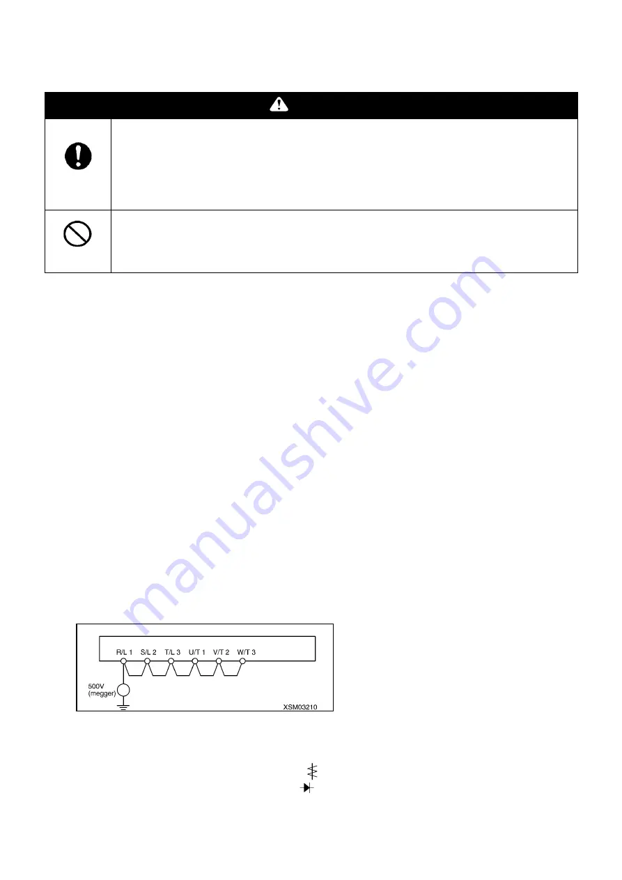
6. When performing insulation tests, use 500V mega, and only perform with the main circuit terminal block as the
target. Never perform insulation tests on control terminals or print boards other than the main circuit. When
performing insulation tests on the motor, disconnect the output terminal U, V, W and perform only on the motor.
When performing insulation tests on surrounding circuits other than the motor, remove all of the wires
connected to the inverter, so that no test voltage flows to the inverter.
(Note) Always remove the wires connected to the main circuit terminal block, and perform on only the inverter
itself.
7. Do not perform pressure tests since it may damage the internal parts.
8. Voltage and temperature check
Recommended amperometer:
Input side
→
moving iron type amperometer (
)
Output side
→
Rectifier type amperometer (
)
It is easier to identify abnormalities if the temperature surrounding the inverter is always measured during the
startup, operation, and stop process.
Summary of Contents for MK0003
Page 2: ......
Page 8: ...0 6...
Page 12: ...1 4 2 DIMENSIONAL DRAWING OF OUTRIGGER WIDTH...
Page 17: ...1 9 4 WORKING RADIUS LIFTING HEIGHT...
Page 18: ...1 10 Working range diagram Outrigger extended to maximum Main boom 1 section...
Page 19: ...1 11 Working range diagram Outrigger extended to maximum Main boom 2 sections...
Page 20: ...1 12 Working range diagram Outrigger extended to maximum Main boom 2 5 sections...
Page 21: ...1 13 Working range diagram Outrigger extended to maximum Main boom 3 sections...
Page 22: ...1 14 Working range diagram Outrigger extended to minimum Main boom 1 section...
Page 23: ...1 15 Working range diagram Outrigger extended to minimum Main boom 2 sections...
Page 24: ...1 16 Working range diagram Outrigger extended to minimum Main boom 2 5 sections...
Page 25: ...1 17 Working range diagram Outrigger extended to minimum Main boom 3 sections...
Page 26: ...1 18 5 RATED TOTAL LOAD CHART...
Page 32: ...2 4...
Page 33: ...2 5 1 HYDRAULIC CIRCUIT DIAGRAM 200 1176600...
Page 34: ...2 6...
Page 35: ...2 7 2 HYDRAULIC PIPING DIAGRAM 2 1 CRANE ROTATING PART 200 1171800...
Page 41: ...2 13 2 2 CONTROL LINE A...
Page 43: ...2 15 2 3CONTROL LINE B Perform spiral winding on the entire perimeter of the hose of this part...
Page 45: ...2 17 2 4 TRAVEL LINE...
Page 47: ...2 19 2 5 OUTRIGGER LINE...
Page 49: ...2 21 2 6 PT LINE 102 1152000 4...
Page 69: ...2 41...
Page 70: ...2 42...
Page 71: ...2 43...
Page 76: ...2 48 4 8 ENGINE ACCESSORIES 102 1149200...
Page 90: ...2 62 7 2 INTERNAL STRUCTURE...
Page 120: ...2 92 Part B Writing method for wire number Two places...
Page 123: ...2 95 Figure 1 Index point Figure 2 Connection diagram...
Page 166: ...2 138 15 4 APPEARANCE OF OUTRIGGER ON REAR LEFT SIDE 200 2167300...
Page 173: ...2 145 17 ELECTRIC CIRCUIT DIAGRAM 200 1176500 01...
Page 174: ...2 146 18 ELECTRIC SYSTEM 18 1 1 WIRE HARNESS OF MACHINE BODY 1 200 1172200 1...
Page 176: ...2 148 18 1 2 WIRE HARNESS OF MACHINE BODY 2 200 1172200 2...
Page 179: ...2 151 19 CONTROL ASSEMBLY 19 1 CONTROLLER 1 TTC60 Pin arrangement...
Page 180: ...2 152 TTC60 I O...
Page 181: ...2 153 2 TTC36X Pin arrangement...
Page 182: ...2 154 TTC36X lower part I O...
Page 209: ...2 181 19 2 5 LIST OF CONTROLLER INPUT MONITORING...
Page 210: ...2 182 19 2 6 LIST OF CONTROLLER ANALOG INPUT OUTPUT MONITORING...
Page 245: ...3 9 1 2 3 ANGLE METER 360 S200M3297000...
Page 274: ...3 38...
Page 293: ...4 19 8 SERVICE LOCATIONS...
Page 294: ...4 20...
Page 296: ...5 2 1 ELECTRICAL MOTOR UNIT ASSEMBLY Unit weight 180 kg...
Page 324: ...5 30...
Page 325: ...5 31 4 ELECTRICAL DIAGRAM S200M3122000 01...
Page 326: ...5 32 S200M3122000 02...
Page 336: ...6 8 1 3 2 INTERNAL STRUCTURE OF WINCH MOTOR...
Page 345: ...6 17 4 WORKING RADIUS LIFTING HEIGHT OF ONE FALL WINCH...
Page 348: ......