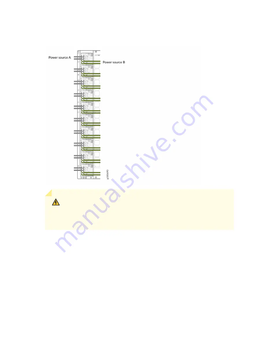
Figure 161: Proper Load Balancing for JNP10K-PWR-DC2 Power Cables on QFX100016
WARNING: Ensure that the power cables do not block access to router
components or drape where people can trip on them. Always prevent cables from
being exposed to hot air exhaust by routing them away from the fan trays and
power supplies at the rear of the chassis.
18. Set the three DIP switches to set the inputs and whether the power supply is running at 3000 W or
at 5500 W. See
Set both enable switches to the on position when using both source inputs. When not using source
redundancy, set the unused source to the O (off) position. The LED turns red and indicates an error
if a source input is not in use and the enable switch is | (on).
313
Summary of Contents for QFX10016
Page 1: ...QFX10016 Switch Hardware Guide Published 2022 09 09...
Page 10: ...Compliance Statements for Environmental Requirements 428 x...
Page 15: ...Figure 1 on page 5 shows a front and rear view of the QFX10016 4...
Page 16: ...Figure 1 QFX10016 Front and Rear 5...
Page 239: ...RELATED DOCUMENTATION QFX10008 Installation Overview QFX10002 System Overview 228...
Page 270: ...1 ESD point Figure 113 ESD Point on QFX10016 Chassis Rear 1 ESD point 259...
Page 287: ...Figure 130 Installing a JNP10K PWR AC2 in a QFX10016 276...
Page 322: ...Figure 159 Installing a JNP10K PWR DC2 in QFX10016 311...
Page 366: ...5 CHAPTER Troubleshooting Troubleshooting QFX10000 Modular Chassis 356...


