2.
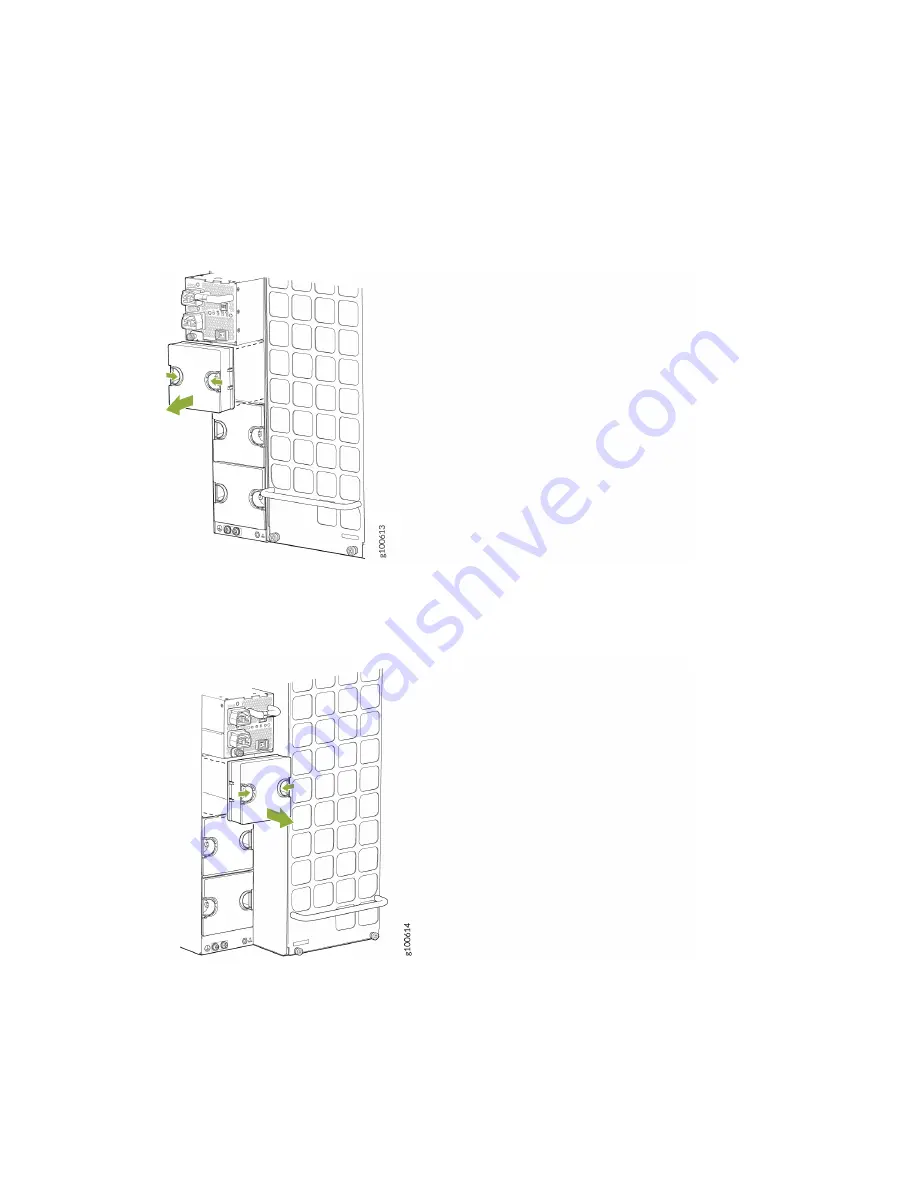
If the power supply slot has a cover panel on it, insert your thumb and forefinger into the finger
holes, squeeze, and pull the cover out of the slot. Save the cover panel for later use. See
for removal on a QFX10008 and
for the QFX10016.
Figure 127: Removing the Power Supply Cover Panel on a QFX10008
Figure 128: Removing the Power Supply Cover Panel on a QFX10016
3.
Taking care not to touch power supply connections, remove the power supply from its bag.
4.
Peel back and remove the protective plastic wrap that covers all four sides of the power supply.
5.
Ensure the power switch is set to the standby (O) position. This switch turns off the output voltage;
it does not interrupt input power.
273
Summary of Contents for QFX10016
Page 1: ...QFX10016 Switch Hardware Guide Published 2022 09 09...
Page 10: ...Compliance Statements for Environmental Requirements 428 x...
Page 15: ...Figure 1 on page 5 shows a front and rear view of the QFX10016 4...
Page 16: ...Figure 1 QFX10016 Front and Rear 5...
Page 239: ...RELATED DOCUMENTATION QFX10008 Installation Overview QFX10002 System Overview 228...
Page 270: ...1 ESD point Figure 113 ESD Point on QFX10016 Chassis Rear 1 ESD point 259...
Page 287: ...Figure 130 Installing a JNP10K PWR AC2 in a QFX10016 276...
Page 322: ...Figure 159 Installing a JNP10K PWR DC2 in QFX10016 311...
Page 366: ...5 CHAPTER Troubleshooting Troubleshooting QFX10000 Modular Chassis 356...


