M-2000® Hardware Manual
©2023 J.A. Woollam Co.
107
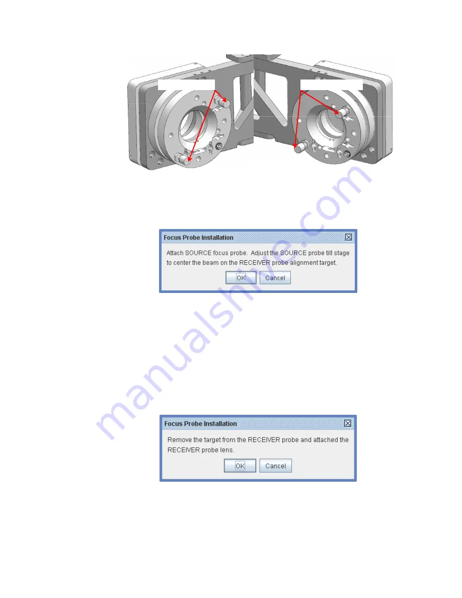
Figure 6-8. Focus Probe Tilt Adjustments.
5.
The second prompt is to attach the Source probe. Using the three
captive thumb screws, attach the Source focusing probe to the Source
probe tilt stage.
Figure 6-9. Adjust Source probe.
6.
Again, observe the ellipsometer beam on the Alignment Target. For
better visibility, reduce the ambient light if possible.
7.
Carefully center the beam on the Alignment Target by translating the
Source side lens with the Vertical Source (VS) and Horizontal Source (HS)
adjustment screws. MOVE THE SOURCE LENS, NOT THE TARGET OR
ELLIPSOMETER BEAM. Click OK when finished.
8.
Follow the next prompt by removing the Alignment Target and replacing
it with the Receiver side lens. Click OK when finished.
Figure 6-10. Remove target.
9.
Lastly, adjust ONLY the RECIEVER LENS (Vertical and Horizontal)
adjustment screws to maximize the Intensity. Click OK when finished and
go to Section 6.3.
Source Lens Adjust
Receiver Lens Adjust
Summary of Contents for M-2000
Page 2: ...2 2023 J A Woollam Co M 2000 Hardware Manual...
Page 4: ......
Page 9: ...M 2000 Hardware Manual 2023 J A Woollam Co ix...
Page 10: ......
Page 50: ......
Page 152: ...152 2023 J A Woollam Co M 2000 Hardware Manual...
Page 172: ......
Page 175: ...M 2000 Hardware Manual 2023 J A Woollam Co 175 M 2000V I M 2000X I...
Page 177: ...M 2000 Hardware Manual 2023 J A Woollam Co 177...


