background image

Working with adapters in the xSeries 330

The server/workstation comes with two peripheral component interconnect (PCI)
adapter slots on the system board with riser cards installed in them.

Attention:

Your server/workstation also comes with an integrated video

controller on the system board. When you install a video adapter in a PCI slot, the
server/workstation BIOS automatically disables the integrated video controller.
This allows the video adapter in the PCI slot to control the video functions for
your monitor.

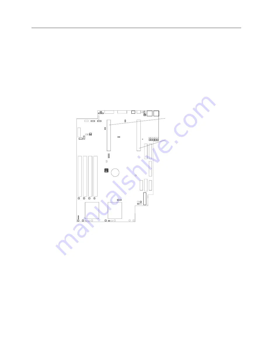
The following illustration shows the location of the 33 MHz PCI expansion slots on
the system board.

Note:

The illustrations in this document might differ slightly from your hardware.

PCI slot 2
64 bit
33 MHz (J23)

PCI slot 1
64 bit
33 MHz (J10)

Adapter considerations

Before you install adapters, review the following:

v

Locate the documentation that comes with the adapter and follow those
instructions in addition to the instructions in this chapter. If you need to change
the switch settings or jumper settings on your adapter, follow the instructions
that come with the adapter.

v

You can install 32-bit or 64-bit full-length or half-length adapters in the
expansion slots. Full-length adapters are installed in slot 1; half-length adapters
are installed in either slot 1 or 2.

v

Your server/workstation supports 5.0 V and universal PCI adapters; it does not
support 3.3 V only adapters.

v

Your server/workstation uses a rotational interrupt technique to configure PCI
adapters. Because of this technique, you can install PCI adapters that currently
do not support sharing of PCI interrupts.

v

PCI slots 1 and 2 and the integrated SCSI controller are on PCI bus B; the
system board and all other integrated devices are on PCI bus A.

Installing options

49

Summary of Contents for 867413x - Eserver xSeries 330 8674

Page 1: ...Hardware Maintenance Manual xSeries 330 Type 8674 IntelliStation R Pro Type 6851 and Network Equipment Building System Type 8674...

Page 2: ......

Page 3: ...Hardware Maintenance Manual xSeries 330 Type 8674 IntelliStation R Pro Type 6851 and Network Equipment Building System Type 8674...

Page 4: ...changes will be incorporated in new editions of the publication IBM may make improvements and or changes in the product s and or the program s described in this publication at any time This publicatio...

Page 5: ...ant This manual is intended for trained servicers who are familiar with IBM PC Server products Before servicing an IBM product be sure to review Safety information on page 147 Important safety informa...

Page 6: ...tuare qualsiasi operazione Lea atentamente todas las declaraciones de precauci n y peligro ante de llevar a cabo cualquier operaci n Online support Use the World Wide Web WWW to download Diagnostic BI...

Page 7: ...t 36 Updating the ASM firmware 36 ASM Firmware Update Utility diskette menu choices 37 Hardware Status and Information 37 Configuration Settings 37 Update System Management Firmware 38 Exit 38 Configu...

Page 8: ...service only 113 Diskette CD ROM drives 113 Diskette CD ROM drive bracket 114 Hard disk drive backplane 115 Power supply 115 PCI riser card 116 System board 116 Important Instructions for the IntelliS...

Page 9: ...the same external storage device s Prior to running diagnostics verify that the failing system is not part of a shared DASD cluster A system might be part of a cluster if v The customer identifies th...

Page 10: ...m Error LED if on see Information panel system error LED on page 121 v Check the System Error Log If an error was recorded by the system see Symptom to FRU index on page 119 v Start the Diagnostic Pro...

Page 11: ...ata storage The xSeries 330 IntelliStation R Pro server workstation comes with a three year limited warranty and IBM server workstation Start Up Support If you have access to the World Wide Web you ca...

Page 12: ...ssions v Sound power idling 6 1 bel maximum v Sound power operating 6 2 bel maximum Electrical input v Sine wave input 50 60 Hz required v Input voltage low range Minimum 100 V ac Maximum 127 V ac v I...

Page 13: ...he system management software for more information v Integrated network environment support The server comes with two Ethernet controllers on the system board Each Ethernet controller has an interface...

Page 14: ...status light amber Hard disk drive activity light green CD eject button CD activity light green Power control button Press this button to manually turn the server on or off Power on light This green L...

Page 15: ...ort Ethernet 1 speed indicator This green LED lights when the speed of the Ethernet LAN that is connected to Ethernet port 1 is 100 Mbps Ethernet 1 link indicator This green LED lights when there is a...

Page 16: ...source Note Plugging the power cord into a power source may cause the server to start automatically This is an acceptable action 2 Wait 30 seconds then press the power control button on the front of...

Page 17: ...de 3 Disconnect the server from the power source Note After turning off the server wait at least 5 seconds before you turn on the server again Stand by mode Stand by puts the server in a wait state Wh...

Page 18: ...10 Hardware Maintenance Manual xSeries 330 Type 8674 IntelliStation R Pro Type 6851 and Network Equipment Building System Type 8674...

Page 19: ...es and messages to indicate successful test completion or the detection of a problem See POST on page 12 for more information v Diagnostic programs and error messages The server workstation diagnostic...

Page 20: ...will not occur the next time you run the test POST error messages The table POST error codes on page 127 provides information about the POST error messages that can appear during startup Event error...

Page 21: ...y the type of error that occurred For LED locations see System board LEDs on page 45 Light Path Diagnostics You can use the Light Path Diagnostics built into your server workstation to quickly identif...

Page 22: ...n the diagnostics panel on the system board See Table 3 for information on identifying problems using these LEDs PS TEMP FAN SP MEM CPU VRM PCI Light Path Table 3 Light Path Diagnostics LED Descriptio...

Page 23: ...he microprocessor ttt is the three digit failure code that indicates the exact test failure that was encountered iii is the three digit device ID date is the date that the diagnostic test was run and...

Page 24: ...board and mouse pointing device tests assume that a keyboard and mouse are attached to the server workstation c If you run the diagnostic programs with no mouse attached to the server workstation you...

Page 25: ...ars press F2 If a power on password is set the server workstation prompts you for it Type in the appropriate password then press Enter 3 When the Diagnostic Programs screen appears select Utility from...

Page 26: ...t your IBM service representative To recover the BIOS 1 Turn off the server workstation and peripheral devices and disconnect all external cables and power cords then remove the cover 2 Locate the BIO...

Page 27: ...d but the problem persists try a different cable If you set the Ethernet controller to operate at 100 Mbps you must use Category 5 cabling If you directly connect two workstations without a hub or if...

Page 28: ...o the Ethernet adapter is also assigned to another device in the Configuration Setup Utility program Although interrupt sharing is allowed for PCI devices some devices do not function well when they s...

Page 29: ...controllers Action Using the Configuration Setup utility make sure that Ethernet is enabled 0x11 Explanation Multiple Ethernet controllers found but none matched the required ID Action Using the Confi...

Page 30: ...Explanation Team nn The last adapter has lost its link Network connection has been lost Action Shut down the server workstation and replace the adapters then restart the server workstation to reestab...

Page 31: ...e AC cord and power on the system If the system powers up successfully replace adapters and devices one at a time until the problem is isolated If system does not power up from minimal configuration r...

Page 32: ...nd disconnect all external cables and power cords 3 Remove the server workstation from the rack see Rack installation on page 46 4 Remove the cover see Removing the cover on page 48 5 Remove the batte...

Page 33: ...0 mm 4 inches at the rear of the server workstation v The top cover is removed for no longer than 30 minutes while the server workstation is operating v A removed hot swap drive is replaced within two...

Page 34: ...26 Hardware Maintenance Manual xSeries 330 Type 8674 IntelliStation R Pro Type 6851 and Network Equipment Building System Type 8674...

Page 35: ...D programs If there is a ServeRAID adapter installed in the server workstation you must use the ServeRAID configuration program to define and configure your disk array subsystem before you install you...

Page 36: ...n Setup Utility menus v System Information Select this choice to display information about the server workstation Changes that you make on other menus might appear on this summary screen You cannot ed...

Page 37: ...t of 0 v System Security Select this choice to set passwords or a system owner s name This choice appears only on the full Configuration Setup Utility main menu You can implement two levels of passwor...

Page 38: ...this choice to enable or disable the microprocessor cache In addition you can set the microprocessor cache mode to write back WB or write through WT Selecting write back mode will provide the maximum...

Page 39: ...or exit without saving the changes Using passwords The System Security choice appears only on the full Configuration Setup Utility menu After you select this choice you can implement two levels of pa...

Page 40: ...next time you start the server workstation the original power on password will be reinstated 4 Connect the server workstation to a power source keyboard monitor and mouse 5 Power up the server workst...

Page 41: ...ting the power on password Using the SCSISelect utility program SCSISelect is a built in menu driven configuration utility program that you can use to v View the default SCSI IDs v Locate and correct...

Page 42: ...ces The transfer rate for Ultra3 SCSI LVD devices is 160 0 The transfer rate for Ultra2 SCSI LVD devices is 80 0 The transfer rate for Fast SCSI devices is 20 0 Advanced Configuration Options Select t...

Page 43: ...s appear on the PXE Boot Agent Utility menu v Network Boot Protocol PXE is the default value for this menu item Note Do not change this value There are no other network boot protocols supported v Boot...

Page 44: ...cessor settings With the configuration utility you can v Configure Alert Setting to enable or disable alert functions v Configure Dial In Out settings v Configure General Settings including the Name a...

Page 45: ...l critical non critical and system alerts supported by the ASM processor Use the arrow keys and the Tab key to move between the fields Use the left and right arrow keys to enable or disable each of th...

Page 46: ...oice to configure the modem that the ASM processor uses Update System Management Firmware Select this choice to update configuration settings for the ASM processor For more information see Updating th...

Page 47: ...s and return to the main menu To return to the main menu without saving press Esc 7 When you are finished using the utility program select Exit Utility from the main menu and press Enter 8 Select Yes...

Page 48: ...40 Hardware Maintenance Manual xSeries 330 Type 8674 IntelliStation R Pro Type 6851 and Network Equipment Building System Type 8674...

Page 49: ...as follows v Notes These notices provide important tips guidance or advice v Important These notices provide information or advice that might help you avoid inconvenient or problem situations v Attent...

Page 50: ...e server workstation Microprocessor Terminator card Fans Hard disk drive filler panel Hard disk drive Memory module Air baffle Light Path Diagnostics Clear shield Heatsink Clip 42 Hardware Maintenance...

Page 51: ...illustration shows the locations of major components in your computer Microprocessor Terminator card Fans Filler panel Hard disk drive Memory module Air baffle Light Path Diagnostics Clear shield Heat...

Page 52: ...U79 DIMM 1 J32 DIMM 2 J34 DIMM 3 J41 DIMM 4 J47 Secondary IDE J2 CD Power J17 BIOS code page jumper J19 Operator information panel J43 Remote Supervisor Adapter J57 System board jumper blocks Any jum...

Page 53: ...n Light path diagnostic panel Fan 1 failure CR15 Fan 3 failure CR31 Fan 5 failure CR40 Fan 4 failure CR33 Fan 6 failure CR48 Fan 2 failure CR17 Microprocessor 1 failure CR26 Microprocessor 2 failure C...

Page 54: ...around the front and rear of the server workstation v Cables for optional adapters are routed according to the instructions provided with the adapters v A failed fan is replaced within 48 hours Workin...

Page 55: ...he front of the server workstation secure the server workstation to the brackets 4 If you have additional servers workstations to install repeat steps 1 through 3 for each server workstation 5 Install...

Page 56: ...r release lever at the back of the server workstation to release the cover 6 Slide the cover back then up and off the server workstation Attention For proper cooling and airflow replace the cover befo...

Page 57: ...efore you install adapters review the following v Locate the documentation that comes with the adapter and follow those instructions in addition to the instructions in this chapter If you need to chan...

Page 58: ...lectricity For details on handling these devices refer to Handling electrostatic discharge sensitive devices on page 150 1 Review the safety precautions that are listed in Related service information...

Page 59: ...latch up to the full open position b Carefully grasp the adapter by its top edge or upper corners and align it with the connector on the PCI riser card c Press the adapter firmly into the riser card c...

Page 60: ...the system board and attach it to the ServeRAID adapter Air flow 10 Install the cover see Removing the cover on page 48 11 Turn on the server workstation 52 Hardware Maintenance Manual xSeries 330 Ty...

Page 61: ...ly from your hardware PCI slot 2 64 bit 33 MHz J23 PCI slot 1 64 bit 33 MHz J10 Adapter considerations If you ever need to install an adapter be sure to review the following v Locate the documentation...

Page 62: ...iding it upward and off the frame of the computer 5 Remove the adapter according to the notes below Notes a For the audio adapter 1 Disconnect the audio cable that connects to the video adapter 2 Slid...

Page 63: ...nsion slot cover 6 Refer to the documentation that comes with your adapter for any cabling instructions Attention You should route adapter cables before you install the adapter 7 Set any jumpers or sw...

Page 64: ...nced System Management ASM firmware DOS configuration utility and management information base MIB from the IBM Support Web site http www ibm com pc support See Advanced System Management on page 36 v...

Page 65: ...oft Windows NT 4 0 Server with Service Pack 4 or later Microsoft Windows 2000 Server Microsoft Windows 2000 Advanced Server SCO UnixWare 7 1 1 or later v Documentation that comes with your server If y...

Page 66: ...Installation Guide this book IBM Remote Supervisor Adapter User s Guide for the xSeries 330 The User s Guide describes the features and functions of the Advanced System Management ASM Web interface an...

Page 67: ...from a list of available topics see brief descriptions of the selected topics and view selected topics using Adobe Acrobat Reader Note The first time you run the Documentation Browser you need to con...

Page 68: ...he Remote Supervisor Adapter in a peripheral component interconnect PCI slot only Inventory checklist The Remote Supervisor Adapter option contains the following items v Remote Supervisor Adapter P P...

Page 69: ...ge to the Ethernet connector on the Remote Supervisor Adapter do not plug the ASM Interconnect module into the Ethernet RJ 45 port v IBM Remote Supervisor Adapter Support CD This CD helps you configur...

Page 70: ...emote Supervisor Adapter to this port to connect the Remote Supervisor Adapter to the other devices on the ASM Interconnect network Power and error LEDs The green power LED indicates the status of the...

Page 71: ...ge 147 2 Turn off the server and attached devices and disconnect all external cables and power cords 3 To remove the cover complete the following steps a Remove the server from the rack if necessary b...

Page 72: ...e PCI slot Be sure it is firmly seated Attention When you install the adapter in the server be sure that it is completely and correctly seated in the system board connector before you apply power Inco...

Page 73: ...pter that comes with the Remote Supervisor Adapter After you connect the power supply adapter to the Remote Supervisor Adapter you can use the power cord to connect the power supply adapter to a prope...

Page 74: ...erfaces that are described in Table 9 on page 66 Choose the interface method you want to use to perform remote management then perform the indicated cabling procedure If you plan to set up an ASM inte...

Page 75: ...ased user interface using the TELNET protocol over PPP Cabling the Ethernet LAN port To attach the Ethernet cables complete the following steps Attention To avoid damage to the Ethernet connector on t...

Page 76: ...Remote Supervisor Adapter firmware on page 68 Updating the Remote Supervisor Adapter firmware You can use the IBM Remote Supervisor Utility program to check the firmware level on the Remote Superviso...

Page 77: ...drive and close the CD ROM drive before the server completes power on self test POST Note If you do not insert the CD and close the CD ROM drive before POST completes you must restart the server with...

Page 78: ...ware 8 When the Remote Supervisor Adapter firmware update process is complete press Enter to return to the Utility program main window Continue with Configuring your system to enable remote access to...

Page 79: ...nd the text based user interface see the IBM Remote Supervisor Adapter User s Guide for the xSeries 330 Configuring the Ethernet settings If you have an accessible active and configured dynamic host c...

Page 80: ...keys to navigate to each field Your system administrator can provide the information for the following fields Network Interface The default value is Enabled verify that it is still set to Enabled IP...

Page 81: ...upervisor Adapter restarts automatically Continue with Completing the installation on page 76 Configuring the serial port To configure the Remote Supervisor Adapter serial port for access using a mode...

Page 82: ...e Configuration Settings window 9 If you need to set up PPP go to Setting up point to point protocol otherwise continue with step 10 10 Press Esc to return to the Utility program main window 11 Use th...

Page 83: ...Up Arrow and Down Arrow keys and to select Configuration Settings then press Enter The Configuration Settings window opens 6 Use the arrow keys to select PPP Settings then press Enter The PPP Setting...

Page 84: ...nterface If you want to set up an ASM interconnect network continue to Planning and cabling your interconnect network on page 77 Your ASM interconnect network can include as many as 12 individual ASM...

Page 85: ...servers to the ASM interconnect network in a series with terminated beginning and end points v Make sure that the total combined length of all Ethernet cables connecting the server in the ASM interco...

Page 86: ...hed When alerts are generated they are forwarded to the Remote Supervisor Adapter ASM processor or ASM PCI adapter on the ASM interconnect network that has the communication resources to forward the a...

Page 87: ...the ASM Interconnect module on servers with ASM processors and ASM PCI adapters see the documentation that comes with those devices To connect the ASM Interconnect module to the Remote Supervisor Adap...

Page 88: ...to the system management administration system that is connected to the network This is an environment that is using all xSeries 330 servers Note You might need to supply additional cables or connecto...

Page 89: ...as the network interconnect forwarding system management data generated by the other systems in the ASM interconnect network bus to the system management administration system that is connected to th...

Page 90: ...management administrator s system Modem Modem Modem ASM Interconnect module xSeries 350 xSeries 220 Remote Supervisor Adapter Hard disk drives The server workstation supports two 1 inch 26 mm slim 3...

Page 91: ...tion has a ServeRAID adapter installed refer to the documentation provided with the ServeRAID adapter for information about adding a drive v Read the safety precautions listed in Safety information on...

Page 92: ...g the drive Replacing a hard disk drive is done in the same manner as installing a new hard disk drive Memory Adding memory to the server workstation is an easy way to improve system performance You c...

Page 93: ...Installing memory modules Complete the following steps to install a DIMM Installing options 85...

Page 94: ...he DIMM connectors do not force the memory module into the connector a Turn the DIMM so that the index slots align correctly with the connector Note The DIMM has two index slots one in the center and...

Page 95: ...can operate as a symmetric multiprocessing SMP server workstation With SMP certain operating systems and application programs can distribute the processing load between the microprocessors This enhanc...

Page 96: ...ils on handling these devices refer to the following Web site and use a search term of ESD http www ibm com 1 Review the safety precautions listed in Safety information on page 147 2 Turn off the serv...

Page 97: ...ctive strip off the bottom of the heat sink Make sure the square of thermal material is still on the bottom of the heat sink b Align and place the heat sink on top of the microprocessor Note Locate th...

Page 98: ...After the clip releases from the heat sink lift it up and off the heat sink Note A thermal material is used between the heatsink and the processor This material when heated and cooled causes the heat...

Page 99: ...e the screws and put them in a safe place 3 Lift the retainer latch up and off the system board b Follow steps 4a on page 90 through 4d on page 90 c After the replacement microprocessor reinstall the...

Page 100: ...lowing illustration shows the replacement of a fan Note The illustrations in this document might differ slightly from your hardware Air flow Complete the following steps to replace the fan assembly 1...

Page 101: ...n b Push the replacement fan assembly into the server workstation until it clicks into place c Connect the fan cable to the system board d If the FAN LED is lit reseat the fan 7 Install the cover see...

Page 102: ...e input output connectors ports and the expansion slots on the rear of the computer For pin assignments and other details about these connectors see Input Output ports Ethernet 1 Ethernet 2 PCI slot 1...

Page 103: ...P N 15941 00 Keyboard connector There is one keyboard connector on the end of the device breakout cable This connector is identified by the keyboard icon Note If you attach a standard non USB keyboard...

Page 104: ...solve address conflicts This serial port is also manually configurable from inside of the computer The following table lists the function of each of the connectors that you can use to manually configu...

Page 105: ...l Serial Bus ports Your computer has two Universal Serial Bus USB ports which configure automatically USB is an emerging serial interface standard for telephony and multimedia devices It uses Plug and...

Page 106: ...t to the network data rate whether the data rate is standard Ethernet 10BASE T Fast Ethernet 100BASE TX half duplex HDX or full duplex FDX The controllers support half duplex HDX and full duplex FDX m...

Page 107: ...k the network devices can base forwarding decisions on priority information defined in the packet Priority Packet information is available on the IBM Networking Web site at http www ibm com networking...

Page 108: ...tions on a system sending packets the packets from the application with a filter are sent out first HPQ does not change network routing nor does it add any information to the packets To assign HPQ you...

Page 109: ...4094 The VLAN name is for information only and does not need to match the name on the switch 7 Repeat steps 3 through 5 for each VLAN you want the computer to join Click on the plus sign next to the...

Page 110: ...ATAPI CD Audio in JST MIC IN LINE IN LINE OUT SPEAKER OUT MIDI Video ports Refer to the video adapter documentation that shipped with your computer for information on the input output connector locat...

Page 111: ...nection Used by OS and Advanced System Management Processor Modem can be connected so that the system can dial out during problems J51 Serial Port B Used by OS only J53 Management Port Used by Advance...

Page 112: ...b to connect the devices The hub provides multiple connectors for attaching additional external USB devices USB technology provides up to 12 megabits per second Mbps speed with a maximum of 127 extern...

Page 113: ...Network adapter as the primary Ethernet controller In failover mode if the primary Ethernet controller detects a link failure all Ethernet traffic associated with it is switched to the redundant secon...

Page 114: ...se packets on your network must support 802 1p for tagging to be effective After you set up the priority filter in Priority Packet you must launch IBMSet and select 802 1p 802 1Q Tagging on the Advanc...

Page 115: ...ws NT 4 0 or later or Novell NetWare 4 1x or later Notes 1 Windows NT versions prior to 4 0 do not support VLANs 2 VLANs require NT 4 0 with Service Pack 3 0 and the NDIS driver hotfix from Microsoft...

Page 116: ...the server workstation to communicate with the integrated Advanced System Management Processor For more information see Serial port on page 103 RS 485 ports The RS 485 ports on the rear of the server...

Page 117: ...maximum of 11 units or servers together v You can hot swap the cables in the ASM bus v Use standard unshielded twisted pair UTP cables with RJ 45 connectors Note For more information about the ASM PCI...

Page 118: ...be used in the C2T chain v The C2T chaining cables are hot swappable Attention Do not let the pins of the C2T cable connectors touch the server chassis when adding or removing systems to or from the C...

Page 119: ...ou will need to test the monitor keyboard and pointing device to be sure that they work with each of the servers Follow these steps to test the C2T cabling 1 Turn on all the servers and the monitor an...

Page 120: ...numbered by their position in the chain 1 through n If one server is removed from the chain all successive servers are renumbered For example if the twelfth server is removed from a chain of 15 serve...

Page 121: ...he diskette CD ROM drive 1 Power off the server workstation 2 Remove the cover See Removing the cover on page 48 3 Disconnect the cables for the floppy disk drive and the CD ROM drive from the system...

Page 122: ...e is removed by gently pulling the cable up until it is released from the connector 2 To replace the diskette drive cable pull up on the connector latch until it is unlocked then insert the end of the...

Page 123: ...connect them from the backplane 5 Remove the screw from the top of the backplane bracket 6 Gently but firmly lift the backplane bracket and board up from the chassis Power supply To remove the power s...

Page 124: ...ation on page 147 and Before you begin on page 45 1 Power off the server workstation 2 Remove the cover See Removing the cover on page 48 3 Disconnect all cables from the system board 4 Remove the ada...

Page 125: ...ate diskette and turn on the system 2 Resolve any configuration or POST startup error messages by following the on screen instructions 3 Select 1 Update POST BIOS from the menu that contains various f...

Page 126: ...118 Hardware Maintenance Manual xSeries 330 Type 8674 IntelliStation R Pro Type 6851 and Network Equipment Building System Type 8674...

Page 127: ...tes the system is functioning properly Beeps Description 1 2 3 v One beep v A pause or break v Two beeps v A pause or break v Three Beeps 4 Four continuous beeps Beep Symptom FRU Action 1 1 2 Processo...

Page 128: ...failed screen believed operable 1 System Board 3 1 1 Timer tick interrupt failed 1 System Board 3 1 2 Interval timer channel 2 failed 1 System Board 3 1 3 RAM test failed above address OFFFFH 1 DIMM 2...

Page 129: ...correctly 1 System Board No beep and no video System Attention LED is OFF 1 See Undetermined problems on page 134 No beep and no video System Attention LED is ON 1 See Information panel system error L...

Page 130: ...ve fan 3 System Board MEM LED on The LED next to the failing DIMM is on 1 DIMM 2 Failing DIMM in slot J1 J4 3 System Board PCI LED on 1 Remove PCI adapters from slots 1 2 2 System Board PS LED on 1 Po...

Page 131: ...d Should connect to Serial Port B on the system board J51 3 System Board 014 XXX 000 Failed Parallel Port test 1 System Board 015 XXX 001 USB interface not found board damaged 1 System Board 015 XXX 1...

Page 132: ...28 is not installed the default when the error occurs 165 330 000 Service Processor Failed 1 Update to the latest ROM diagnostic level and retry 165 342 000 Service Processor Failed 1 Ensure latest fi...

Page 133: ...ive with SCSI ID NN 3 Tape Drive with SCSI ID NN Refer to the Help and Service Information appendix of the tape drive s User Guide 4 System Board or SCSI Controller Run SCSI Controller Diagnostic to d...

Page 134: ...IBM monitors have their own self tests If you suspect a problem with the monitor refer to the information that comes with the monitor for adjusting and testing instructions 1 Monitor 2 Run Video Diag...

Page 135: ...eal time clock battery error 1 Run Configuration Setup 2 Battery 3 System Board 162 Device Configuration Error Note Be sure to load the default settings and any additional desired settings then save t...

Page 136: ...ptional Processor if installed 262 DRAM parity configuration error 1 Run configuration setup 2 Battery 3 System Board 289 DIMM has been disabled by the user or system see Memory Settings on page 30 1...

Page 137: ...the Service Processor but the Service Processor failed to respond at the start of POST 1 Do the following before replacing a FRU a Remove the ac power to the system wait 20 seconds then re connect th...

Page 138: ...cessor 2 2 System Board 00180200 No more I O space available for PCI adapter 1 Run Configuration Setup 2 Failing Adapter 3 System Board 00180300 No more memory above 1MB for PCI adapter 1 Run Configur...

Page 139: ...SCSI device adapter drive controller v An improper SCSI configuration or SCSI termination jumper setting v Duplicate SCSI IDs in the same SCSI chain v A missing or improperly installed SCSI terminator...

Page 140: ...ature level warning system reporting under temperature condition for CPU X 1 Ambient temperature must be within normal operating specifications see Features and specifications on page 4 Fan error mess...

Page 141: ...ture outside recommended operating range 1 Ensure system is being properly cooled see Temperature checkout on page 25 2 Replace SCSI Backplane System shutoff due to high ambient temperature level crit...

Page 142: ...power switch Note If AC power has been removed from system allow 30 seconds after restoring AC power before pressing power control button See Turning on the server on page 8 Note If system was powered...

Page 143: ...f problem goes away replace removed items one at a time until failing item is found power on and reconfigure system each time Notes 1 If the problem goes away when you remove an adapter from the syste...

Page 144: ...136 Hardware Maintenance Manual xSeries 330 Type 8674 IntelliStation R Pro Type 6851 and Network Equipment Building System Type 8674...

Page 145: ...Parts listing xSeries 330 The xSeries 330 parts listing supports Type 8674 models 11X 12X 13X 31X 32X 33X 3AX 41X 42X 43X 44X N1X Copyright IBM Corp 2001 137...

Page 146: ...11X 12X 13X 31X 32X 33X 3AX 41X 42X 43X 44X N1X FRU Number 1 Bracket Baffle All Models 00N6993 2 Heat Sink Clip Assembly All Models 24P0653 138 Hardware Maintenance Manual xSeries 330 Type 8674 Intel...

Page 147: ...l Models 00N7021 Rail Assembly All Models 00N6994 External Interface Adapter Bracket All Models 00N6995 Battery 3 0 Volt 8590 All Models 33F8354 Heatsink clip All Models 06P6240 18 2 GB SCSI Fixed 10K...

Page 148: ...adian 37L2552 LA Spanish 37L2553 Arabic 37L2555 Belgium French 37L2556 Belgium UK 37L2557 Bulgarian 37L2558 Czech 37L2559 Danish 37L2560 Dutch 37L2561 French 37L2562 German 37L2563 Greek 37L2564 Hebre...

Page 149: ...ublic Egypt Finland France French Guyana Germany Greece Guinea Hungary Iceland Indonesia Iran Ivory Coast Jordan Lebanon Luxembourg China Macao S A R Malagasy Mali Martinique Mauritania Mauritius Mona...

Page 150: ...6851 parts listing supports model types 10x 11x 12x 13x 20x 21x 22x 23x 1 2 3 4 5 6 7 8 9 10 11 12 13 14 15 16 17 18 142 Hardware Maintenance Manual xSeries 330 Type 8674 IntelliStation R Pro Type 68...

Page 151: ...ssembly All Models 76H6620 Keyboard Models 10x 11x 20x 21x 37L2551 Matrox G200 Video Adapter NTSC Models 10x 11x 20x 21x 25P1899 Matrox G200 Video Adapter PAL Models 12x 13x 22x 23x 25P2461 IBM Audio...

Page 152: ...nish 37L2560 Dutch 37L2561 French 37L2562 German 37L2563 Greek 37L2564 Hebrew 37L2565 Hungarian 37L2566 Korean 02K0901 Iceland 37L2567 Italy 37L2568 Norwegian 37L2569 Polish 37L2570 Portuguese 37L2571...

Page 153: ...ance French Guyana Germany Greece Guinea Hungary Iceland Indonesia Iran Ivory Coast Jordan Lebanon Luxembourg China Macao S A R Malagasy Mali Martinique Mauritania Mauritius Monaco Morocco Mozambique...

Page 154: ...146 Hardware Maintenance Manual xSeries 330 Type 8674 IntelliStation R Pro Type 6851 and Network Equipment Building System Type 8674...

Page 155: ...ses hazards to the customer or that makes the equipment unsafe v Before you start the machine ensure that other service representatives and the customer s personnel are not in a hazardous position v P...

Page 156: ...hazardous voltages v Disconnect all power before Performing a mechanical inspection Working near power supplies Removing or installing main units v Before you start to work on the machine unplug the p...

Page 157: ...t become a victim yourself Switch off power Send another person to get medical aid Safety inspection guide The intent of this inspection guide is to assist you in identifying potentially unsafe condit...

Page 158: ...se product specific ESD procedures when they exceed the requirements noted here 2 Make sure that the ESD protective devices you use have been certified ISO 9000 as fully effective When handling ESD se...

Page 159: ...n statement appear in this section under statement 1 Be sure to read all caution and danger statements before performing any of the instructions v Statement 1 DANGER Electrical current from power tele...

Page 160: ...posed of Do not v Throw or immerse into water v Heat to more than 100 C 212 F v Repair or disassemble Dispose of the battery as required by local ordinances or regulations v Statement 3 CAUTION When l...

Page 161: ...pply do not turn off the electrical current supplied to the device The device also might have more than one power cord To remove all electrical current from the device ensure that all power cords are...

Page 162: ...al esse produto ser conectado a tomadas corretamente instaladas v Sempre que poss vel utilize apenas uma das m os para conectar ou desconectar cabos de sinal v Nunca ligue qualquer equipamento quando...

Page 163: ...iar a bateria pelo correio para a IBM Instru o 3 PRECAUCI N Quando produtos a laser unidades de CD ROM unidades de DVD dispositivos de fibra tica transmissores etc estiverem instalados observe o segui...

Page 164: ...tivo tamb m pode ter mais de um cabo de alimenta o Para remover toda a corrente el trica do dispositivo assegure que todos os cabos de alimenta o estejam desconectados da fonte de energia el trica 1 2...

Page 165: ...Related service information 157...

Page 166: ...158 Hardware Maintenance Manual xSeries 330 Type 8674 IntelliStation R Pro Type 6851 and Network Equipment Building System Type 8674...

Page 167: ...Related service information 159...

Page 168: ...160 Hardware Maintenance Manual xSeries 330 Type 8674 IntelliStation R Pro Type 6851 and Network Equipment Building System Type 8674...

Page 169: ...Related service information 161...

Page 170: ...162 Hardware Maintenance Manual xSeries 330 Type 8674 IntelliStation R Pro Type 6851 and Network Equipment Building System Type 8674...

Page 171: ...Related service information 163...

Page 172: ...164 Hardware Maintenance Manual xSeries 330 Type 8674 IntelliStation R Pro Type 6851 and Network Equipment Building System Type 8674...

Page 173: ...c bl s tout quipement connect ce produit v Lorsque cela est possible n utilisez qu une seule main pour connecter ou d connecter les c bles d interface v Ne mettez jamais un quipement sous tension en c...

Page 174: ...nit s de CD ROM ou de DVD des p riph riques contenant des fibres optiques ou des metteurs r cepteurs prenez connaissance des informations suivantes v N ouvrez pas ces produits pour viter une expositio...

Page 175: ...imentation ne coupent pas l arriv e de courant lectrique l int rieur de la machine Il se peut que votre unit dispose de plusieurs cordons d alimentation Pour isoler totalement l unit du r seau lectriq...

Page 176: ...takt anschlie en v Signalkabel m glichst einh ndig anschlie en oder l sen v Keine Ger te einschalten wenn die Gefahr einer Besch digung durch Feuer Wasser oder andere Einfl sse besteht v Die Verbindun...

Page 177: ...e Einheiten mit Glasfaserkabeln oder Transmitter installiert ist beachten Sie folgendes v Das Entfernen der Abdeckungen des CD ROM Laufwerks kann zu gef hrlicher Laserstrahlung f hren Es befinden sich...

Page 178: ...f r den Server nicht unterbrochen Der Server k nnte auch mehr als ein Netzkabel aufweisen Um die gesamte Stromversorgung des Servers auszuschalten mu sichergestellt werden da alle Netzkabel aus den Ne...

Page 179: ...are qualsiasi apparecchiatura collegata a questo prodotto ad una presa elettrica correttamente cablata e munita di terra di sicurezza v Quando possibile collegare o scollegare i cavi di segnale con un...

Page 180: ...do si installano prodotti laser come ad esempio le unit DVD CD ROM a fibre ottiche o trasmettitori prestare attenzione a quanto segue v Non rimuovere i coperchi L apertura dei coperchi di prodotti las...

Page 181: ...o sull alimentatore non disattiva la corrente elettrica fornita all unit L unit potrebbe disporre di pi di un cavo di alimentazione Per disattivare la corrente elettrica dall unit accertarsi che tutti...

Page 182: ...174 Hardware Maintenance Manual xSeries 330 Type 8674 IntelliStation R Pro Type 6851 and Network Equipment Building System Type 8674...

Page 183: ...Related service information 175...

Page 184: ...176 Hardware Maintenance Manual xSeries 330 Type 8674 IntelliStation R Pro Type 6851 and Network Equipment Building System Type 8674...

Page 185: ...tomas de alimentaci n con un cableado correcto cualquier equipo que vaya a estar conectado a este producto v Si es posible utilice una sola mano cuando conecte o desconecte los cables de sent al v No...

Page 186: ...CI N Cuando instale productos l ser como por ejemplo CD ROM unidades DVD dispositivos de fibra ptica o transmisores tenga en cuenta las advertencias siguientes v No retire las cubiertas Si retira las...

Page 187: ...gan la corriente el ctrica suministrada al dispositivo Es posible tambi n que el dispositivo tenga m s de un cable de alimentaci n Para eliminar la corriente el ctrica del dispositivo aseg rese de des...

Page 188: ...to see added changed or deleted in this manual ________________________________________________________________ ________________________________________________________________ 3 What is your service...

Page 189: ...Have the same adapters attachments in the same locations 4 Have the same address jumpers terminators cabling 5 Have the same software versions and levels 6 Have the same Reference Diagnostics Diskette...

Page 190: ...I Xeon are trademarks of Intel Corporation in the United States other countries or both Microsoft Windows and Windows NT are trademarks of Microsoft Corporation in the United States other countries or...

Page 191: ......

Page 192: ...Part Number 24P2923 1P P N 24P2923...

Reviews: