5 WIRING
- 47 -
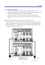
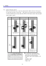
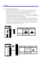
5.6.2 Examples of remote I/O cable wiring
In the following example of wiring, cables having different characteristics are connected to the
RI/O-1 and RI/O-2 ports on the CPU module.
•
Connect terminating resistors, as described in “5.6.3 Setting terminating resistors.”
•
Connect ground lines, as described in “5.3 Wiring for Grounding.”
HITACHI
S10mini
LQP000
LADDER
MODE
PROTECT
RESET
STOP
RUN
SIMU
NORM
OFF
ON
CPU-S
LQS000
HITACHI
HSC-1000
RI/O
LQS000
HITACHI
HSC-1000
RI/O
A
(
A4
)
B
(
A5
)
SHD
(
A6
)
COM
(
A8
)
100
Ω
(
A9
)
A
(
A4
)
B
(
A5
)
SHD
(
A6
)
150
Ω
(
A7
)
COM
(
A8
)
150
Ω
(
B4
)
A
(
B6
)
B
(
B7
)
SHD
(
B8
)
100
Ω
(
A6
)
A
(
A7
)
B
(
A8
)
SHD
(
A9
)
LQS000
HITACHI
HSC-1000
RI/O
A
(
A4
)
B
(
A5
)
SHD
(
A6
)
RI/O-1
A
(
B5
)
B
(
B6
)
SHD
(
B7
)
RI/O-2
RI/O-1
RI/O-1
LQS000
HITACHI
HSC-1000
RI/O
A
(
A4
)
B
(
A5
)
SHD
(
A6
)
RI/O-1
A
(
B5
)
B
(
B6
)
SHD
(
B7
)
RI/O-2
Setting for termination
with a 150
Ω
resistor
CPU module
(RI/O-1: Terminated with a 100
Ω
resistor)
(RI/O-2: Terminated with a 150
Ω
resistor)
Setting for termination
with a 100
Ω
resistor
RI/O-1
RI/O cable: 100 m or less
(CO-SPEV-SB-1P)
100
Ω
Setting for termination
with a 150
Ω
resistor
RI/O station module
(not terminated)
RI/O station module
(terminated with a 100
Ω
resistor)
Setting for termination
with a 100
Ω
resistor
RI/O-2
RI/O cable: 200 m or less
(CO-EV-SB 1P × 0.18SQ)
150
Ω
RI/O station module
(not terminated)
RI/O station module
(terminated with a 150
Ω
resistor)
R/IO
U
L
STND
R/IO
U
L
STND
R/IO
U
L
STND
R/IO
U
L
STND
CPU RUN
Assigned numbers on the terminal block
Signal
CPU module
RI/O module
RI/O1
RI/O2
RI/O1
RI/O2
150
Ω
A5 B4 A7
⎯
100
Ω
A6 B5 A9
⎯
COM
⎯
⎯
A8
⎯
A A7 B6 A4 B5
B A8 B7 A5 B6
SHD A9 B8 A6 B7
Summary of Contents for S10mini D
Page 1: ......
Page 14: ...THIS PAGE INTENTIONALLY LEFT BLANK ...
Page 19: ...1 BEFORE USE ...
Page 28: ...THIS PAGE INTENTIONALLY LEFT BLANK ...
Page 29: ...2 OVERVIEW ...
Page 34: ...THIS PAGE INTENTIONALLY LEFT BLANK ...
Page 35: ...3 NAMES AND FUNCTIONS OF PARTS ...
Page 45: ...4 INSTALLATION ...
Page 54: ...THIS PAGE INTENTIONALLY LEFT BLANK ...
Page 55: ...5 WIRING ...
Page 68: ...THIS PAGE INTENTIONALLY LEFT BLANK ...
Page 69: ...6 SETTING ...
Page 84: ...THIS PAGE INTENTIONALLY LEFT BLANK ...
Page 85: ...7 OPERATION PROCEDURES ...
Page 91: ...8 EXPLANATION OF OPERATION ...
Page 111: ...9 MAINTENANCE ...
Page 128: ...THIS PAGE INTENTIONALLY LEFT BLANK ...
Page 129: ...10 SPECIFICATIONS ...

