8 EXPLANATION OF OPERATION
- 92 -
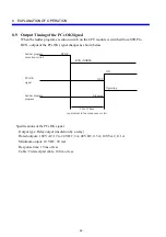
8.9 Output Timing of the PCs OK Signal
When the ladder program execution switch on the CPU module is switched from STOP to
RUN, output of the PCs OK signal changes as shown below.
RUN (NORM)
STOP
OFF
ON
Ladder program
execution switch
PCs OK
signal
Ladder diagram
program
90 to 120 ms
(equivalent to four sequence cycles)
Stopping
Operating
Specifications of the PCs OK signal
Output type: Relay output (insulation by a relay)
Rated outputs: 100 VAC; 12 to 24 VDC, 2A; 48 VDC, 0.5 A; 100 VAC, 0.1 A
Minimum output: 10 VDC, 20 mA
Response time: 15 ms or less
Cable: Twisted-pair cable, 100 m or less
Summary of Contents for S10mini D
Page 1: ......
Page 14: ...THIS PAGE INTENTIONALLY LEFT BLANK ...
Page 19: ...1 BEFORE USE ...
Page 28: ...THIS PAGE INTENTIONALLY LEFT BLANK ...
Page 29: ...2 OVERVIEW ...
Page 34: ...THIS PAGE INTENTIONALLY LEFT BLANK ...
Page 35: ...3 NAMES AND FUNCTIONS OF PARTS ...
Page 45: ...4 INSTALLATION ...
Page 54: ...THIS PAGE INTENTIONALLY LEFT BLANK ...
Page 55: ...5 WIRING ...
Page 68: ...THIS PAGE INTENTIONALLY LEFT BLANK ...
Page 69: ...6 SETTING ...
Page 84: ...THIS PAGE INTENTIONALLY LEFT BLANK ...
Page 85: ...7 OPERATION PROCEDURES ...
Page 91: ...8 EXPLANATION OF OPERATION ...
Page 111: ...9 MAINTENANCE ...
Page 128: ...THIS PAGE INTENTIONALLY LEFT BLANK ...
Page 129: ...10 SPECIFICATIONS ...

