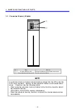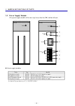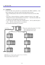
3 NAMES AND FUNCTIONS OF PARTS
- 21 -
No.
Name
Function
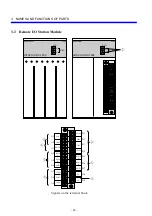
①
Station number setting switches
Each sets a station number. Set the first two digits of the I/O number as follows:
higher-order digit using the U-switch and low-order digit using the L-switch.
②
Input/output point count setting
Selects the number of input/output points occupied by one slot on the mount base (16,
32, 64, or 128).
③
FIX/FREE setting
Defines the partition of the mount base as free or fixed.
④
Output holding
Selects one of the output states RESET or HOLD which the output modules enters when
the remote I/O line is broken.
⑤
RI/O line input
Used to connect the remote I/O cable defined as upper level.
⑥
RI/O line branching
Used to connect the remote I/O cable defined as lower level.
⑦
Terminating resistor setting
Terminates the station module through a built-in terminating resistance (100
Ω
or 150
Ω
)
when the station module is connected as the last module on the remote I/O line. When
using a non-specified remote I/O cable, see “5.6.3 Setting terminating resistors.”
⑧
Frame ground
Connects the remote I/O cable to the FG terminal on the mount base to ground the cable.
• For details of the settings, see “6 SETTINGS.”
• For details of connection, see “5 WIRING.”
Summary of Contents for S10mini D
Page 1: ......
Page 14: ...THIS PAGE INTENTIONALLY LEFT BLANK ...
Page 19: ...1 BEFORE USE ...
Page 28: ...THIS PAGE INTENTIONALLY LEFT BLANK ...
Page 29: ...2 OVERVIEW ...
Page 34: ...THIS PAGE INTENTIONALLY LEFT BLANK ...
Page 35: ...3 NAMES AND FUNCTIONS OF PARTS ...
Page 45: ...4 INSTALLATION ...
Page 54: ...THIS PAGE INTENTIONALLY LEFT BLANK ...
Page 55: ...5 WIRING ...
Page 68: ...THIS PAGE INTENTIONALLY LEFT BLANK ...
Page 69: ...6 SETTING ...
Page 84: ...THIS PAGE INTENTIONALLY LEFT BLANK ...
Page 85: ...7 OPERATION PROCEDURES ...
Page 91: ...8 EXPLANATION OF OPERATION ...
Page 111: ...9 MAINTENANCE ...
Page 128: ...THIS PAGE INTENTIONALLY LEFT BLANK ...
Page 129: ...10 SPECIFICATIONS ...


