6 SETTING
- 63 -
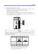
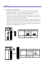
Example of setting station numbers and I/O numbers
Suppose that one CPU unit and four I/O units are installed in different locations. Then set station
numbers and I/O numbers, as shown below.
I/O
1 X420 to 42F
2 X430 to 43F
3 X440 to 44F
4 X450 to 45F
5 Y420 to 42F
6 Y430 to 43F
7 Y440 to 44F
8 Y450 to 45F
PS
I/O
1 000 to 00F
2 010 to 01F
CPU
PS
I/O
1 020 to 02F
2 030 to 03F
RI/O
ST
RI/O
ST
RI/O
ST
RI/O
ST
PS
I/O
1 400 to 40F
2 410 to 41F
PS
I/O
1 040 to 04F
2 050 to 05F
3 060 to 06F
4 070 to 07F
PS
ST.NO=“00”
U: 0
L: 0
ST.NO=“02”
U: 0
L: 2
ST.NO=“04”
U: 0
L: 4
ST.NO=“40”
U: 4
L: 0
ST.NO=“42”
U: 4
L: 2
RI/O-1
RI/O-2
Station number
CPU unit
(2 slots, 16-point modules)
Slot number
I/O numbers
(In practice, each number listed here is prefixed
with one of the letters X or Y:)
X000 to X00F
Y000 to Y00F
I/O unit
(2 slots, 16 points, FREE)
I/O unit
(2 slots, 16 points, FREE)
I/O unit
(8 slots, 16 points, FREE)
I/O unit
(4 slots, 16 points, FREE)
I/O numbers
(In practice, each number listed here is prefixed
with one of the letters X or Y:)
X000 to X00F
Y000 to Y00F
I/O numbers
(In practice, each number listed here is prefixed
with one of the letters X or Y:)
X000 to X00F
Y000 to Y00F
Summary of Contents for S10mini D
Page 1: ......
Page 14: ...THIS PAGE INTENTIONALLY LEFT BLANK ...
Page 19: ...1 BEFORE USE ...
Page 28: ...THIS PAGE INTENTIONALLY LEFT BLANK ...
Page 29: ...2 OVERVIEW ...
Page 34: ...THIS PAGE INTENTIONALLY LEFT BLANK ...
Page 35: ...3 NAMES AND FUNCTIONS OF PARTS ...
Page 45: ...4 INSTALLATION ...
Page 54: ...THIS PAGE INTENTIONALLY LEFT BLANK ...
Page 55: ...5 WIRING ...
Page 68: ...THIS PAGE INTENTIONALLY LEFT BLANK ...
Page 69: ...6 SETTING ...
Page 84: ...THIS PAGE INTENTIONALLY LEFT BLANK ...
Page 85: ...7 OPERATION PROCEDURES ...
Page 91: ...8 EXPLANATION OF OPERATION ...
Page 111: ...9 MAINTENANCE ...
Page 128: ...THIS PAGE INTENTIONALLY LEFT BLANK ...
Page 129: ...10 SPECIFICATIONS ...


