9 MAINTENANCE
- 103 -
Diagnosis by replacing modules
If the cause of the failure cannot be corrected by diagnosis by checking the operation indicator LED
status and the message in the indicator, replace the module as described below.
Module to replace
Failure
Action
Power supply module
The LED does not light.
Replace the power supply module.
None of the I/O modules does not operate.
Replace the CPU module
I/O module
The I/O modules in the I/O unit do not operate.
Replace the station module.
Only a particular I/O module does not operate.
Replace the I/O module.
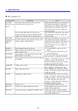
Error messages (1/3)
Error Message
Explanation
Action
CPU DOWN
CPU down
A fatal error occurred when the OS was
running. See the displayed error message and
repair.
CPU CELL
Battery low
Replace the backup battery (ER6T-3WK41-Z).
SSP OVER
Program running abnormally
WDT ERR
Ladder program stagnation monitoring-detected error
OS PTY
OS process memory parity error
(1) Press the RESET switch on the CPU
module.
(2) Turn on the power switch on the power
supply module again.
If the error condition persists even after the
above procedure is performed, clear all the
memory. For information on how to clear the
memory, see pages 106 through 109.
If clearing of the memory does not solve the
problem, replace the CPU module.
If
∆∆
is one of the values 10-4F, the error is an
extension memory parity error.
Clear all the memory. Then, if the same error
recurs, replace the extension memory. For
information on how to clear the memory, see
pages 106 through 109.
EX
∆∆
PTY
∆∆
: See the 105
pages (*).
If
∆∆
is a value other than 10-4F, the error is a parity
error detected during reading by the CPU module of
the optional module’s internal memory.
Press the RESET switch on the CPU module.
Then, if the same error recurs, replace the
optional module.
EXMD PTY
(displayed along
with ROM
IDLE)
The error is a parity error detected during reading by
the CPU module of extension memory or the optional
module’s internal memory.
Handle the ROM IDLE error according to the
information supplied under “Diagnosis by
checking the power indicating LED status and
the message in the indicator” on pages 102.
Then, clear all the memory. For information
on how to clear the memory, see pages 106
through 109.
If clearing of the memory does not solve the
problem, replace the extension memory or
optional module.
Summary of Contents for S10mini D
Page 1: ......
Page 14: ...THIS PAGE INTENTIONALLY LEFT BLANK ...
Page 19: ...1 BEFORE USE ...
Page 28: ...THIS PAGE INTENTIONALLY LEFT BLANK ...
Page 29: ...2 OVERVIEW ...
Page 34: ...THIS PAGE INTENTIONALLY LEFT BLANK ...
Page 35: ...3 NAMES AND FUNCTIONS OF PARTS ...
Page 45: ...4 INSTALLATION ...
Page 54: ...THIS PAGE INTENTIONALLY LEFT BLANK ...
Page 55: ...5 WIRING ...
Page 68: ...THIS PAGE INTENTIONALLY LEFT BLANK ...
Page 69: ...6 SETTING ...
Page 84: ...THIS PAGE INTENTIONALLY LEFT BLANK ...
Page 85: ...7 OPERATION PROCEDURES ...
Page 91: ...8 EXPLANATION OF OPERATION ...
Page 111: ...9 MAINTENANCE ...
Page 128: ...THIS PAGE INTENTIONALLY LEFT BLANK ...
Page 129: ...10 SPECIFICATIONS ...


