8 EXPLANATION OF OPERATION
- 74 -
8.1 Ladder Diagram Program
8.1.1 Execution
Execution conditions
• CPU operation switch (LADDER): RUN
• Mode switch (MODE): NORM or SIMU
(In SIMU mode, only the ladder diagram program is executed
without remote I/O transfer being performed.)
Starting the ladder diagram program
The ladder diagram program can be started in one of two ways: cyclically or repeatedly.
• Cyclic start
If the specified sequence cycle time is longer than the processing time taken by the ladder
diagram program, it starts at the interval equal to the sequence cycle time. Upon
completion of processing by the ladder diagram program, it waits until the next start time
comes. This method is used for integration, differential, and other operations.
• Repeated start
If the specified sequence cycle time is shorter than the processing time taken by the ladder
diagram program, the sequence cycle time is used only for the first start. Then, the
ladder diagram program starts at the interval equal to its processing time. Upon
completion of processing by the ladder diagram program, control is returned to the
starting point of the ladder diagram program to execute it repeatedly.
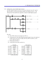
X000
X010
X012
X001
X007
X020
X004
Y004
X015
X017
ADD
Y035
Start timer
Start
End
F
XW100 + XW110 = YW040
Summary of Contents for S10mini D
Page 1: ......
Page 14: ...THIS PAGE INTENTIONALLY LEFT BLANK ...
Page 19: ...1 BEFORE USE ...
Page 28: ...THIS PAGE INTENTIONALLY LEFT BLANK ...
Page 29: ...2 OVERVIEW ...
Page 34: ...THIS PAGE INTENTIONALLY LEFT BLANK ...
Page 35: ...3 NAMES AND FUNCTIONS OF PARTS ...
Page 45: ...4 INSTALLATION ...
Page 54: ...THIS PAGE INTENTIONALLY LEFT BLANK ...
Page 55: ...5 WIRING ...
Page 68: ...THIS PAGE INTENTIONALLY LEFT BLANK ...
Page 69: ...6 SETTING ...
Page 84: ...THIS PAGE INTENTIONALLY LEFT BLANK ...
Page 85: ...7 OPERATION PROCEDURES ...
Page 91: ...8 EXPLANATION OF OPERATION ...
Page 111: ...9 MAINTENANCE ...
Page 128: ...THIS PAGE INTENTIONALLY LEFT BLANK ...
Page 129: ...10 SPECIFICATIONS ...


