9 MAINTENANCE
- 97 -
9.2 Replacing the Backup Battery
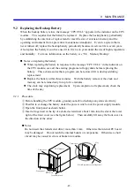
When the backup battery is low, the message “CPU CELL” appears in the indicator on the CPU
module. This requires that the battery be replaced. Replace the backup battery periodically
by establishing the intervals of replacement to meet the size of extension memory and the
operating environment from a preventive maintenance standpoint. Even in a system that is
never turned off, replace the backup battery periodically because its service life is seven years.
Also replace the battery if you have used it in five to six years under the use of high temperature
and humidity. For more information on the battery, see “8.8 Memory Backup.”
Notes on replacing the battery
When replacing the battery in response to the message “CPU CELL” in the indicator on
the CPU module, save all the existing programs to floppy disks before replacing the
battery. This action assures that a program can be restored if it is destroyed during
replacement.
Replace the battery within three minutes. With the battery removed, the clock and
memory can be retained only for up to five minutes.
The clock may stop during replacement. Upon completion of replacement, check the
time of the day.
9.2.1 Procedure
①
Before handling the CPU module, ground yourself to discharge any static electricity.
②
Possible to exchange the battery under the power switch on of the power supply module.
③
Open the front panel as shown below.
④
Insert a finger nail or the tip of a slotted screwdriver about 1 mm into the slot at the lower
right of the front cover (see the figure below). Then carefully lift away the front cover in
the direction of the arrow.
Notes
Do not insert the slotted screwdriver more than 1 mm. Otherwise the internal PC board
may be damaged. Do not touch the internal boards or components. Otherwise a short
circuit may be caused to errors or broken in module.
Slotted screwdriver or finger nail
Front cover
CPU module
Front panel
Open in
this direction.
Terminal block
Front cover
Slot
Summary of Contents for S10mini D
Page 1: ......
Page 14: ...THIS PAGE INTENTIONALLY LEFT BLANK ...
Page 19: ...1 BEFORE USE ...
Page 28: ...THIS PAGE INTENTIONALLY LEFT BLANK ...
Page 29: ...2 OVERVIEW ...
Page 34: ...THIS PAGE INTENTIONALLY LEFT BLANK ...
Page 35: ...3 NAMES AND FUNCTIONS OF PARTS ...
Page 45: ...4 INSTALLATION ...
Page 54: ...THIS PAGE INTENTIONALLY LEFT BLANK ...
Page 55: ...5 WIRING ...
Page 68: ...THIS PAGE INTENTIONALLY LEFT BLANK ...
Page 69: ...6 SETTING ...
Page 84: ...THIS PAGE INTENTIONALLY LEFT BLANK ...
Page 85: ...7 OPERATION PROCEDURES ...
Page 91: ...8 EXPLANATION OF OPERATION ...
Page 111: ...9 MAINTENANCE ...
Page 128: ...THIS PAGE INTENTIONALLY LEFT BLANK ...
Page 129: ...10 SPECIFICATIONS ...


